
Quick Start Guide


| Quick Start Guide | Camden TAC IP 100 Series Entry System
3
Caution
Never make or break connections to the TAC IP 100 unless it and all associated
components are powered off and disconnected from electrical outlets.
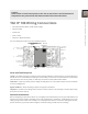
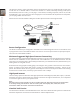
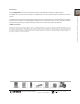
TAC IP 100 Wiring Connections
• Recommended PS133UP +12VDC Power Supply
• Ethernet Cable
• Postal Lock
• Door Contact
• Request to Exit Device (RTE)
For more wiring information, see the installation section.
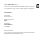
Parts and Tools Required
Laptop - this will be required to remotely access network hardware. A laptop may be connected directly to
the TAC IP 100 via a CAT5 Ethernet cable (part of this toolkit), connected to a local network via external hub
(often located at the security desk), or wirelessly connected via CPU powered Wi-Fi switch.
CAT5 cable - required to directly connect laptop to lobby phone or to insert Wi-Fi switch onto local network
in front of lobby phone.
Digital Volt Meter - allows checking for power and signal on hardware.
Cell phone - needed to test calling, audio, and door control functions. The concierge or another phone may
be used if one exists close by.
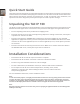
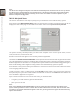
Network Installations
Before attempting to operate the TAC IP 100, it is highly recommended that you have your LAN network and
Internet Connection installed, including access and conguration to the Router. A LAN will afford you the
ability to program the TAC IP 100 remotely from a Laptop and the Internet connection will register services,
permit the factory to provide technical support and allow testing of VOIP services for dialing.
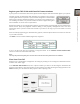
2 x22 AWG per
Door Contact
RTE
PIR
Postal Local
Tamper
Switch
5 x 22 AWG
Shielded Card
Reader
3 x 22 AWG Shielded
Wiegand Output 2
3 x 22 AWG Shielded
Wiegand Output 1
EthernetUSB 1/2+5V
Power
2 x 18 AWG
Aux Device
2 x 18 AWG Elevator
Call Button
2 x 18 AWG 12V DC
Power Supply
3 x 22 AWG
Shielded RS485
2 x 18 AWG Door
Strike Maglock
Power/ Reset/ Recovery
Buttons
MicroSD Card