
Installation Manual

Section 1__________________
General Description
The PC-6 is a dual purpose relay designed to be used with
safety sensors, and swing-door operators.
1. The PC-6 functions as a lock-out relay (LOR) for full-speed
doors with header (lintel) mount safety sensors. In this
application, the sensor is “lockedout” during the closing
cycle by the relay. (The safety sensor is engaged at all other
times). In order to meet the ANSI code, provision is made
for railmounted photo-eyes (sold separately).
2. The second application is as a Secondary Activation
Module (SAM) for low energy doors, which are activated by
a push-switch (called Knowing Act doors). In this case the
safety sensor is mounted on the approach side of the door
leaf.
The principle is that when the door is opened manually the
safety sensor is not in the circuit, and the door operator
essentially functions as a manual door closer.
However, when a user pushes the activating switch, the
PC-6 immediately sends a signal to the operator, opening
the door, and putting the door mounted sensor into the
circuit. This allows an object or person in the path of the
door to be detected. The door will not close until the object
or person leaves the door swing path. The sensor remains
in the circuit until the door is closed, allowing for maximum
safety. A door position switch (magnetic contact switch) is
required.
FEATURES / BENEFITS:
One relay does two different applications.
No jumpers or switches to select, or traces to cut – mode
selection is automatic.
Operates on any voltage from 12 – 24V AC/DC.
Works with any operator – AC or DC motors, Electro-
mechanical, or Electro-hydraulic.
CX-PC-6
(replaces PC3 and PA5)
Installation Instructions
5502 Timberlea Blvd.
Mississauga, Ontario L4W 2T7
905-366-3377 Toll Free: 877-226-3369
www.camdencontrols.com
Section 2__________________
Installation
Mounting
The PC-6 should be mounted in a clean dry location out of
direct contact with the elements. Once the unit has been
wired and adjusted, it may be tucked up in the header or
affixed using the supplied Velcro.
Wiring
CAUTION: Do not apply power to the unit until all
secondary wiring is complete.
Wiring of this unit is dependant on the mode desired.
Select your intended application, then proceed to the
section indicated.
WIRING & SET-UP INSTRUCTIONS:
Lock-out Relay Proceed to section 3A below
(replaces PC-3)
Secondary Activation Module Proceed to section 3B on
(replaces PA-5) Page 2
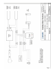
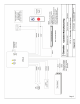
Section 3A________________
Wiring & Set Up Instructions
Lock-out Relay Mode
The two Orange wires are used to power the PC-6, and
can be connected to 12 or 24 volts, AC/DC. (Non polarity
sensitive). The yellow LED glows faintly to indicate power.
The Red and Black wires connect directly to the door motor
leads (between the control box and motor).