M Series Multi-Output Access Control Power Supply Chargers Installation Guide Models Include: • AL300ULM - 2. 5 amp @ 12VDC or 24VDC. • AL400ULM - 3 amp @ 12VDC or 4 amp @ 24VDC. • AL600ULM - 6 amp @ 12VDC or 24VDC. • AL1012ULM - 10 amp @ 12VDC. • AL1024ULM - 10 amp @ 24VDC. For a red enclosure, add an “R” suffix to the part # e.g. AL300ULMR Rev.
Overview: These multi-output access control power supply/chargers are specifically designed for use with access control systems and accessories. These units convert a 115VAC / 60Hz input into five (5) individually protected 12VDC or 24VDC outputs (see specifications). Each output will route power to a variety of access control hardware devices including Mag Locks, Electric Strikes, Magnetic Door Holders, etc. These outputs will operate in both Fail-Safe and Fail-Secure modes.
Spe cifica t ions (cont ’d): Visual Indicators: Supervision (cont’d): • DC output LED indicator. • LEDs indicate condition of power outputs. • Power & input trigger LED’s. • Battery presence supervision (form “C” contact). • Power fail supervision relay (form “C” contact rated 1 amp @ 28VDC). • Power supply is complete with enclosure, cam lock, transformer and battery leads. Supervision: • AC fail supervision (form "C" contact). • Low battery supervision (form "C" contact).
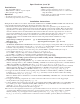
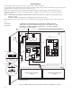
11.Connect supervisory trouble reporting devices to outputs marked [AC FAIL, LOW BAT] and [Power Fail] supervisory relay outputs marked [NO, C, NC] on power supply board (Fig. 1A, pg. 5; Fig. 2A, pg. 6; Fig. 3A, pg. 7; Fig. 4A, pg. 8). Use 22 AWG to 18 AWG for AC Fail & Low Battery reporting. Note: When used in fire alarm, burglar alarm or access control applications, “AC Fail” relay must be used to provide a visual indication of AC power on. 12.
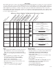
M aintenance: Unit should be tested at least once a year for the proper operation as follows: Output Voltage Test: Under normal load conditions, the DC output voltage should be checked for proper voltage level (Output Voltage and Stand-by Specification Charts, pg. 4). Battery Test: Under normal load conditions check that the battery is fully charged, check specified voltage at the battery terminals and at the board terminals marked [+ BAT--] to insure that there is no break in the battery connection wires.
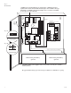
Fig. 2 AL600ULM CAUTION: De-energize unit prior to servicing. For continued protection against risk of electric shock and fire hazard replace fuses with the same type and rating (see marking on the board). Replace fuse cover before energizing. Do not expose to rain or moisture.
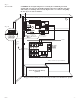
Fig. 3 AL1012ULM CAUTION: De-energize unit prior to servicing. For continued protection against risk of electric shock and fire hazard replace fuses with the same type and rating (see marking on the board). Replace fuse cover before energizing. Do not expose to rain or moisture. Door Fig. 3A NC C NO NC C NO Fuse Cover Green Lead 115VAC power mains non-power limited Class 1 Battery and AC Supervision Circuit (power limited).
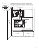
Fig. 4 AL1024ULM NO Fig. 4A C NC NO C CAUTION: De-energize unit prior to servicing. For continued protection against risk of electric shock and fire hazard replace fuses with the same type and rating (see marking on the board). Replace fuse cover before energizing. Do not expose to rain or moisture. NC Battery and AC Supervision Circuit (power limited).
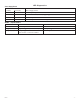
LED Diagnostics: Power Supply Board Red (DC) LED Green (AC) Power Supply Status ON ON Normal operating condition. ON OFF Loss of AC, Stand-by battery supplying power. OFF ON No DC output. Short circuit or thermal overload condition. OFF OFF No DC output. Loss of AC. Discharged battery. M OM 5 - Output M odule LED Power (Green) Trigger (Green) Outputs (Red) Mseries ON Normal operation. Input is triggered (alarm condition). Output tripped due to a short circuit or overload condition.
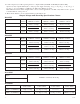
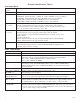
Terminal Identification Tables: Power Supply Board Terminal Legend Function/Description L, G, N Connect 115VAC 60Hz to these terminals: L to hot, N to neutral, G to ground. - DC + AL300ULM - 12VDC/24VDC @ 2.5 amp to MOM5 board (power limited). AL400ULM - 12VDC @ 4 amp or 24VDC @ 3 amp to MOM5 board (power limited). AL600ULM - 12VDC/24VDC @ 6 amp to MOM5 board (non-power limited). AL1012ULM - 12VDC @ 10 amp to MOM5 board (non-power limited). AL1024ULM - 24VDC @ 10 amp to MOM5 board (non-power limited).
Typical Application Diagrams: Fig. 5 MOM5 module shown with wet and/or dry nor- (+) (-) MOM5 module shown with wet and/or dry normally open trigger inputs (Non-Latching): DC VOLTAGE INPUT FROM FACP SIGNALING OUTPUT OR ACCESS CONTROL DEVICE NEG (-) INPUT POS (+) NEG (-) INPUT POS (+) mally closed trigger inputs (Non-Latching): (+) (-) DC VOLTAGE INPUT FROM FACP SIGNALING OUTPUT OR ACCESS CONTROL DEVICE N.C. INPUT FROM FACP OR ACCESS CONTROL DEVICE EOL 2.2K TRIGGER TRIGGER EOL 2.2K N.O.
Typical Application Diagrams (cont’d.): MOM5 module shown with with wet and/or dry normally open fire alarm trigger inputs (Latching with Manual Reset): (+) (-) MOM5 module shown with with wet and/or dry normally closed fire alarm trigger inputs (Latching with Manual Reset): DC VOLTAGE INPUT FROM FACP SIGNALING OUTPUT NEG (-) INPUT POS (+) NEG (-) INPUT POS (+ Fig. 8 (-) DC VOLTAGE INPUT FROM FACP SIGNALING OUTPUT TRIGGER TRIGGER EOL 2.2K (+) N.O.
Enclosure Dim e nsions: • AL300ULM • AL400ULM • AL600ULM 13.5”H x 13”W x 3.25”D 1.40" 4.85" 4.85" 1.40" 1.20" 3.25" Top 12.50" 1.20" 0.75" 1.20" 0.75" 11.00" 0.9375" 1.40" 1.40" 5.10" 5.10" Left Right 5.10" 6.5625" 0.9375" 3.25" 3.25" Bottom 3.25" 1.00" 1.00" 1.00" Mseries 10.50" 1.
Enclosure Dimensions: • AL1012ULM • AL1024ULM 15.5”H x 12”W x 4.5”D 1.285 1.
Notes: Mseries - 15 -
Notes: Altronix is not responsible for any typographical errors. Altronix Corp. 140 58th Street, Brooklyn, New York 11220 USA, 718-567-8181, fax: 718-567-9056 web site: www.altronix.com, e-mail: info@altronix.com, Lifetime Warranty, Made in U.S.A.