AUTOMATION SYSTEMS FOR SLIDING GATES BX SERIES INSTALLATION MANUAL BX-10
“IMPORTANT INSTALLATION, SAFETY INSTRUCTIONS” “CAUTION: IMPROPER INSTALLATION MAY CAUSE SERIOUS DAMAGE, FOLLOW ALL INSTALLATION INSTRUCTIONS CAREFULLY” “THIS MANUAL IS ONLY FOR PROFESSIONAL OR QUALIFIED INSTALLERS” 1 Legend of symbols ENGLISH This symbol tells you to read the section with particular care. This symbol tells you that the sections concern safety issues. 2 Conditions of use 2.1 Intended use The BX10 operator is designed to power sliding gates in residential and condominium settings.
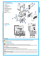
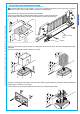
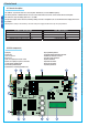
1 4 1 - Top cover 2 - Settings casing 3 - Control board support 4 - Endstop fins 5 - ZBX10 electronic card 6 - Front cover to control panel 7 - Gearmotor release door 8 - Securing plate 9- Securing bolt 10- Securing screw plate 11- Nut 2 ENGLISH The data and information shown in this dialogue may be changed by Came Cancelli Automatici S.p.A. at any time without prior warning. 4.3 Description of parts 3 6 5 11 7 2 10 8 9 4.
5.2 Tools and materials 5.3 Cable list and minimum thickness Connection Type of cable Length of cable 1 < 10 m Leng. cable 10 < 20 m Leng. cable 20 < 30 m Control panel power supply 230V 3G x 1,5 mm2 3G x 2,5 mm2 3G x 4 mm2 Flashing light 2 x 0,5 mm2 2 x 1 mm2 2 x 1,5 mm2 2 x 0,5 mm2 2 x 0.
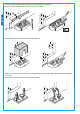
.5 Securing the plate and installing the assembly The following applications are only examples, as the space for installing the ratiomotor and accessories varies according to obstructions. It is thus up to the system installer to select the most suitable solution. The data and information shown in this dialogue may be changed by Came Cancelli Automatici S.p.A. at any time without prior warning. ENGLISH - Dig a pit to the side of the gate (see measurements from diagram).
H - Remove the form box, fill the pit around the cement block with soil. - Unbolt the nuts and washers from the bolts. The securing plate must be clean, perfectly aligned and with the bolt threads completely on the surface. Insert the electric cables into the tubes until they exit about 400mm. 6 The data and information shown in this dialogue may be changed by Came Cancelli Automatici S.p.A. at any time without prior warning.
- Remove the cover from the gearmotor by loosening the side bolts, perforate the cable shafts using a screwdriver or a pair of scissors and position the gearmotor atop the plate. Careful! The electric cables must pass through the cable shafts. ENGLISH The data and information shown in this dialogue may be changed by Came Cancelli Automatici S.p.A. at any time without prior warning.
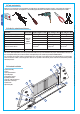
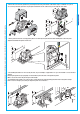
- Open and close the gate manually and register the pinion-to-rack distance using the threaded steel-levelling feet (for vertical adjusting) and the slotted holes (horizontal adjusting). This prevents the weight of the gate from bearing on the operator. ENGLISH Rack Rack Levelling feet The data and information shown in this dialogue may be changed by Came Cancelli Automatici S.p.A. at any time without prior warning.
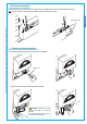
5.6 Mounting the endstop fins Place the endstop fins onto the rack and secure them using a 3 mm Allen wrench. Their positioning limits the gate run. Note: the gate schould not slam against the mechanical stop, when opening or closing. ENGLISH The data and information shown in this dialogue may be changed by Came Cancelli Automatici S.p.A. at any time without prior warning. Mechanical stop 5.7 Manually releasing the gearmotor - Insert the trilobed key into the lock, push it in and turn it clockwise ....
6 Control board Use 230V A.C. to power the electronic card using the L-N terminals, at a max 50/60Hz frequency. Use 24V to power the command devices and accessories. Careful! The accessories cannot exceed 37W of overall power. All connections are protected by quick-fuses – see table. The input and output contact functions, the timing settings and users’ management, are set and viewed on the display, which is run by software.
6.3 Electrical connections Gearmotor, endstop and encoder Description of the standard electrical connections for left-hand installations ENGLISH Orange COM Black Red White NC The data and information shown in this dialogue may be changed by Came Cancelli Automatici S.p.A. at any time without prior warning. 230V (A.C.
Movement flashing light (Contact range: 230V – 25W max) - Flashes during the gate’s opening and closing phases. Open-gate status light (contact range: 24V – 3W max) - Signal that gate is open; turns off when gate is closed. Cycle lamp: (contact rating: 230V – 60W max.). It lights up the driving area and stays on from the moment the gate begins to open until it is fully closed (including the automatic closing time).
Safety devices RX Configure either (N.C.) contacts CX or CY, input for safety devices such as photocells, that comply with EN 12978 standards. See CX or CY input functions in: - C1 «re-open during closing phase», When the gate leaf is closing, opening the contact triggers the inversion of the direction of movement until the gate leaf is fully open.
6.4 Electrical connection to operate the photocells’ safety test (DIR) # . # . / ENGLISH (DOC) 48 # .# 48 48 At each open/close command, the card check the photocells’ efficiency. Any problems with the photocells will cause the (PROG) Led to flash on the electronic card, which cancels any commands from the radio transmitter or push-button.
7 Programming 7.1 Description of display commands The <> keys are for: - shifting from one menu item to another - increase or decrease values { ENGLISH WWW.CAME.IT The data and information shown in this dialogue may be changed by Came Cancelli Automatici S.p.A. at any time without prior warning. The ESC key is for: - exiting the menu - cancelling modifications The ENTER key is for: - entering the menu - confirming and memorising set values the <...
7.3 Menu structure < LANGUAGE > ENTER < FUNCTIONS > ENGLISH > > > > > > ENTER > ENTER < > A.C.T. < 10s > ENTER > > > See detailed description on page 28 ENTER < 11s > > < Cycle Time > < 90s > ENTER > > > < < 91s > Slowdown > < 10% > ENTER > > < 5s > ENTER > > > < 11% > > > < 6s > ENTER < -ooooo+ > ••• > >
< Autom.Clos. > < ON > ENTER > < OFF > > > < 2-7 Command > ENTER Preflash > < ON > ENTER The data and information shown in this dialogue may be changed by Came Cancelli Automatici S.p.A. at any time without prior warning. > < OFF > > > ENGLISH < > > > < ON > ENTER > < OFF > > >
7.3 Main menu LANGUAGE English FUNCTIONS TIMING ADJ. INFO ADJUSTMENTS RADIO USRS 7.4 Language menu Select language: selects among the languages displayed. < LANGUAGE > English LANGUAGE < English > LANGUAGE < Deutsch > LANGUAGE < Francais > FUNCTIONS TIMING IMING ADJ ADJ. LANGUAGE < Italiano > RADIO ADIO USRS LANGUAGE < Espanol > ADJUSTMENTS DJUSTMENT INFO 7.5 Functions menu Automatic Closing: activates or deactivates the automatic closing function.
Pre-flashing: after an opening or closing command, the flashing light, connected to W-E1, starts flashing before the gate begins its run (to set the time, see “Pre-flashing timing” from the Adjust Timings menu < LANGUAGE > English h X2 < FUNCTIONS Preflash > < OFF > X2 RADIO USR USRS Preflash ON > < The data and information shown in this dialogue may be changed by Came Cancelli Automatici S.p.A. at any time without prior warning.
CY input: N.C. safety contact input, lets you pair up the following functions: C1 (re-opening during closing), C2 (re-closing during opening), C3 (partial stop), C4 (obstacle stall), or, deactivated < LANGUAGE > English h X6 < FUNCTIONS CY Input > Disabled CY Input Disabled < > < CY Input C1 > < CY Input C2 > ENGLISH TIMING AD ADJ. ADJUSTMENTS DJUSTMEN < INFO CY Input C4 > X2 < CY Input C3 > C7 input: N.C. safety contact input (re-opening when closing).
Safety test: Allows the card to check the efficiency of any safety devices (i.e. photocells) after every opening or closing command. < LANGUAGE > English h X10 < FUNCTIONS Safety Test Disable > < Safety Test Disable > Safety Test RADIO USR USRS Safety Test < En.on CX + CY > ADJUSTMENTS DJUSTMEN The data and information shown in this dialogue may be changed by Came Cancelli Automatici S.p.A. at any time without prior warning.
7.6 Time setting menu Automatic closing: to set the waiting time when gate is in the open position. Once this time is elapsed, the gate closes automatically. The waiting time can be set to between 0” and 120”. < LANGUAGE > English h < TIMING ADJ. RADIO USR USRS A.C.T 10 s > < A.C.T. 10 s > X2 ADJUSTMENTS DJUSTMEN < A.C.T. 11 s > INFO Working time: the motor’s working time during opening or closing; from 10” to 120”. < LANGUAGE > English h FUNCTION FUNCTIONS < TIMING ADJ.
Users Radio Menu New user: to create a new user and assigned function (see detailed function on page 27). The user will be assigned a number (max. 250 users) with a function. < LANGUAGE > English h < New User Related Func. < 2-7 Function > > TIMING AD ADJ. The data and information shown in this dialogue may be changed by Came Cancelli Automatici S.p.A. at any time without prior warning. RADIO USRS R S < Related Func. Only Open > X2 Related Func.
Load memory: to load the data saved on the memory roll onto card X4 < LANGUAGE > English h Reading ooooooo ••• < Restore backup > FUNCTION FUNCTIONS ENGLISH TIMING AD ADJ. RADIO USRS R S ADJUSTMENTS DJUSTMEN The data and information shown in this dialogue may be changed by Came Cancelli Automatici S.p.A. at any time without prior warning. INFO Cancel all: to cancel all registered users. Confirm cancellation of all users with ENTER. < LANGUAGE > English h X5 TIMING AD ADJ.
Deceleration speed: to adjust the deceleration speed when opening and closing. < LANGUAGE > English h X2 -ooooo+ ••• FUNCTION FUNCTIONS Slow.Down Spd. -ooooo+ < > ••• TIMING AD ADJ. ENGLISH RADIO USR USRS X2 Slow.Down Spd. -ooooo+ < > •••• ADJUSTMENTS The data and information shown in this dialogue may be changed by Came Cancelli Automatici S.p.A. at any time without prior warning.
Brake force: to calibrate the braking force on the gate during run-inversions and at endstops. < LANGUAGE > English h X6 < FUNCTION FUNCTIONS Brake Force -oooo+ • Brake Force -oooo+ > • > < ENGLISH TIMING AD ADJ. RADIO USR USRS X2 ADJUSTMENTS < Brake Force -oooo+ > • Web address: to define the master card or slave in paired connections (see detailed function on page 29). < LANGUAGE > English h X7 < NET address > Disabled FUNCTION FUNCTIONS NET address < Disabled > TIMING AD ADJ.
7.10 Decoding card Insert the (AF43S) radio card which command the operator and insert, modify or remove any users using the transmitter. Insert the memory roll to save and upload the registered users onto another card. TFM AF Card CAM E ENGLISH The data and information shown in this dialogue may be changed by Came Cancelli Automatici S.p.A. at any time without prior warning. TAM Memory roll Frequency/MHz Card Transmitter FM 26.995 AF130 TFM FM 30.900 AF150 TFM AM 26.995 AF26 TOP AM 30.
7.12 Modifying user (modifying the function) ENGLISH 1) From the Users Radio menu, select “Modify User”. Press ENTER to confirm. Þ 2) Select the user number or name for which you wish to modify the assigned function and press ENTER to confirm. ß Modify User Modify User Þ n.001 In use ß n.002 In use 4) ...once you have selected the function to assign, you will get the “Modify User” readout... 3) Select the assigned function. n.002 Existing Þ 2-7 Function ß Þ n.
7.14 Net address The data and information shown in this dialogue may be changed by Came Cancelli Automatici S.p.A. at any time without prior warning. RSE card RSE card 1) On the Master card. From the Calibration Menu, select “NET address” and press ENTER. Þ NET address 2) Select “Master” and press ENTER to confirm the calibration. NET address ß Þ Disabled Disabled ß NET address Þ Master ß 3) Select “Slave” for another card.
8 Safety instructions This product must only be employed for its originally intended use. Any other use is wrong and potentially dangerous. The manufacturer cannot be held liable for any damages resulting from wrongful, erroneous or negligent uses. Avoid working close to the hinges or other moving mechanical parts. Stay out of the opening/closing arc when operator is in motion. Do not exercise force against the motion of the operator as this could result in potentially dangerous situations.
9 Maintenance Periodic maintenance to be carried out by the end-user is as follows: wipe clean the glass surface of the photocells; check that the safety devices work properly; remove any obstructions. We suggest checking the state of lubrication and tightness of the anchoring screws on the operator. -To check the efficiency of the safety devices, move an object in front of the photocells when gate is closing. If the operator inverts the motion or stops, the photocells are working properly.
Periodic maintenance log for end-user (every 6 moths) Notes Signature 9.3 Extra-ordinary maintenance The following table serves to note down any extraordinary maintenance, repairs or improvements performed by specialised firms. N.B.: Any extraordinary maintenance must be performed by specialised technicians.
Installer’s stamp Operator name Date of job Technician’s signature Requester’s signature Installer’s stamp ENGLISH Job performed________________________________________________________________________________________ __________________________________________________________________________________________________ Operator name The data and information shown in this dialogue may be changed by Came Cancelli Automatici S.p.A. at any time without prior warning.
CAME UNITED KINGDOM LTD UNIT 3, ORCHARD BUSINESS PARK TOWN STREET, SANDIACRE NOTTINGHAM - NG10 5BP - U.K. Tel - 0044 115 9210430 Cod. 119BU57 ver. 0.1 09/07 © CAME cancelli automatici s.p.a.