AUTOMATION SYSTEM FOR SLIDING GATES BX241 INSTALLATION MANUAL
“IMPORTANT SAFETY INSTRUCTIONS FOR INSTALLATION” “CAUTION: IMPROPER INSTALLATION MAY CAUSE SERIOUS DAMAGE, FOLLOW ALL INSTALLATION INSTRUCTIONS CAREFULLY” “THIS MANUAL IS ONLY FOR PROFESSIONAL INSTALLERS OR QUALIFIED PERSONS” 1 Legend ENGLISH This symbol indicates sections to be read with particular care. This symbol indicates sections concernig safety This symbol indicates notes to communicate to users.
4.
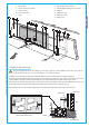
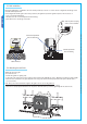
5 Installation Installation must be carried out by expert qualified personnel and in full observance of regulations in force. Before proceeding with the installation, it is necessary to: • Make sure the door is rigid and compact and that the sliding wheels are well oiled and in good condition. • The ground guide must be well fastened to the ground, fully on the surface for the entirety of its length and without irregularities that might obstruct the gate’s movement.
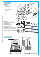
12345- 67891011- 5.4 Motor to base anchorage The following applications are only examples, as the space required for unit installation and the accessories vary depending on dimensions and therefore it is up to the installer to select the best solution. - Install the screws in the anchor plate and fasten them with a nut, then bend the preformed clamps downwards.
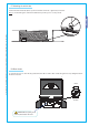
5.5 Unit installation Rack-to-pinion coupling with 1÷2 mm clearance ¿ MM Horizontal adjustment and unit anchorage Vertical adjustment and unit leveling Cable entrances 5.6 Attaching the rack/limit Attach the rack to the gate as described below: - Release the gearmotor (parag. 5.
5.7 Attaching the switch tabs Position the limit-switch tabs (whose positions determine the limits of gate travel) on the rack. Note: do not allow the gate to strike the mechanical stops in the open or closed positions. All the data and information contained herein is considered subject to change at any time and at our discretion ENGLISH CAME 5.8 Gear release To open the access door, insert the key, push down and rotate clockwise. Now, release the gear motor by rotating the knob in the direction shown.
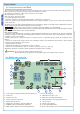
6 Control board ENGLISH This control board is powered by 230V a.c. across terminals L1 and L2, and is protected by a 1A fuse on the main power line. Control systems are powered by low voltage and protected with by a 1.6A fuse. The total power consumption of 24V accessories must not exceed 40 W. Fixed operating time of 90 seconds.
6.3 Description board BN1 The BN1 board allows the automation to be battery operated in case of a power outage. When power is restored, the card also recharges the batteries. 2 $ # " ! 1 ENGLISH ". 6.4 Emergency battery connection Insert batteries in the appropriate bracket (Fig.1) and connect them (using the cables provided) to the ZBX241 board (Fig.2) terminal (+,-). FIG.1 FIG.2 12V - 1.
6.6 Electrical connections 24V AC + L2 L1 L2 - M N FA FC F 10 11 E1 1 2 3 3P C1 C3 7 230V (a.c.) power supply M N M 24V(d.c.) motor 11 E 24V output in motion (e.g. flashing light 25W) +10 -11 24V powering accessories max. 40W 1 2 Pushbutton stop (N.C.) 2 3 Pushbutton open (N.O.) 2 3P Pushbutton partial opening (N.O.) 2 7 Contact radio and/or pushbutton for controlled (see dip-switch 2-3) 2 C1 Contact (N.C.) for «re-aperture during closure» 2 C3 Contact (N.C.
6.7 Function selections ON OFF /.
7.2 Procedure for codifying the transmitter TOP QUARTZ SERIES 1 assign a code (also on file) 0 /&& 0 /. 2 connect encoding jumper J Press P1 or P2 in sequence in order to register the code; at the tenth pulse, a double beep will confirm that registration has occurred 3 register code 4 disinserire jumper J 0 TOP T262M - T302M 0 The first encoding operation must be carried out whilst keeping the jumpers positioned for channels 1 and 2 as per fig. A; see fig.
T2622M - T3022M T264M - T304M P1 = CH1 P2 = CH2 0 0 1° Code 0 0 P1 = CH1 P2 = CH2 P3 = CH3 ENGLISH P4 = CH4 0 0 0 0 0 /&& 0 /. 2° Code All the data and information contained herein is considered subject to change at any time and at our discretion P3 = CH1 P4 = CH2 TOP SERIES TOP T432M - T312M D 0 0 set the code to dip-switch C and channel to D (P1=CH1 and P2=CH2, default setting) P1 /.
ATOMO SERIES AT01 - AT02 - AT04 see instruction sheet inside the pack of AF43SR circuit card ENGLISH CAM E TOUCH SERIES see instructions on pack L2 L1T L2T 24V AC + M - N FA FC F 10 11 E1 1 2 3 3P C1 C3 7 •• BATTERY • • • • •• • • 7.3 Memorizing the code on the command board A Flashing LED D • • • • • • •• • • • • • C B 1) Keep the "CH1" key pressed on the base card, the signal LED will flash. PROGRAM. CH1 + T.A.C. - + SENS.
8 Maintenance The unit does not require specific maintenance. Only as a precautionary measure and in case of intensive use, we recommend periodic checks (every 6 months) on the state of the electric wire connected to the motor, the tightness of the nuts and the proper oiling of the sliding points between fixed and mobile parts. All checks must be recorded (in a dedicated record-book).
CAME UNITED KINGDOM LTD UNIT 3, ORCHARD BUSINESS PARK TOWN STREET, SANDIACRE NOTTINGHAM - NG10 5BP - U.K. Tel 0044 115 9210430 Cod. 119BS30 ver. 3.