
Manual

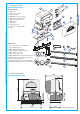


The following applications are only examples, as the space required for unit installation and the accessories vary de-
pending on dimensions and therefore it is up to the installer to select the best solution.
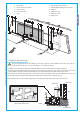
5.4 Motor to base anchorage
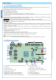
1- BX-241 unit
2- Control board incorporated
3- Radio receiver
4- Limit-switch tabs
5- Rack
6- Key-operated selector switch
7- Flashing light indicating door movement
8- Antenna
9- Safety photocells
10- Photocell column
11- Closure stop
5
All the data and information contained herein is considered subject to change at any time and at our discretion
ENGLISH
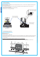
- Install the screws in the anchor plate and fasten them with a nut, then bend the preformed clamps downwards.
- Construct a cement foundation that is large enough to accomodate the gear motor (it is a good idea to protrude 50 mm. from the
ground). When pouring the foundation, embed the gear motor anchor plate and the relative clamps in the cement.
- The anchor bolts should be embedded in the concrete in the positions indicated; the drive unit is then attached to this bots. The
anchor plate must be perfectly level and absolutly clean; the bolts threads must be completly exposed.
N.B.: The fl exible tubes for the electrical wiring must be embedded in the base and protude in the correct position.
MM
MM
MM
Fixing plate / Anchor stays
Cables
Concrete base
Rack-limit
Gate wing
Wall