AUTOMATION FOR SWING GATES FERNI SERIES INSTALLATION MANUAL F1024 N
“IMPORTANT INSTALLATION, SAFETY INSTRUCTIONS” “CAUTION: IMPROPER INSTALLATION MAY CAUSE SERIOUS DAMAGE, FOLLOW ALL INSTALLATION INSTRUCTIONS CAREFULLY” “THIS MANUAL IS ONLY FOR PROFESSIONAL OR QUALIFIED INSTALLERS” 1 Legend of symbols ENGLISH This symbol tells you to read the section with particular care. This symbol tells you that the sections concern safety issues. 2 Intended use and restrictions 2.
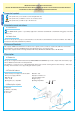
4.4 Overall dimensions Measurements in mm 5 Installation Installation must be carried out by expert qualified personnel and in full compliance with current regulations. 5.1 Preliminary checks Before installing, do the following: • Make sure the structure of the gate is sturdy, the hinges work and that the is no friction between moving and non-moving parts; • That measurement C is not greater than the value shown in Tab. 3, p. 4.
5.2 Tools and materials 5.3 Cable list and minimum thickness Connections Type of cable Length of cable 1 < 10 m Leng. cable 10 < 20 m Leng. cable 20 < 30 m Control panel power supply 230V 2F 3G x 1,5 mm2 3G x 2,5 mm2 3G x 4 mm2 Flashing light 230V 2 x 0,5 mm2 2 x 1 mm2 2 x 1,5 mm2 2 x 0,5 mm2 2 x 0.
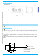
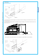
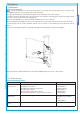
.5 Mounting Pillar ENGLISH Ø 8 mm Ø 14 mm Ø 8 mm - secure the base plate to the pillar using ø8 screws and ø14 moulded inserts making sure the minimum distance of 150mm from the ground is met. - Secure the A bracket (using ø8 screws or by welding) to the gate leaf making sure the 450mm and 19mm distances measurements and are met. 450 mm Front view 19 150 mm The data and information shown in this manual may be changed by CAME cancelli automatici s.p.a. at any time without prior warning.
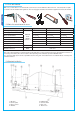
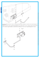
Fig. 2 6 The data and information shown in this manual may be changed by CAME cancelli automatici s.p.a. at any time without prior warning. ENGLISH - Insert the straight semi-arm into the motor shaft. Apply the flared washer, the M6x20 screw and lock the semi-arm using the two grub screws. Join and secure the two arms using the washer and M8x16 screw. Release the motor (see p. 13) and secure the curved semi-arm to the “A” bracket using the M12X50 screw and the M12 nut making sure it runs freely.
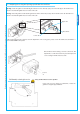
5.7 Adjusting the closing and opening-speed brake microswitches Opening: release the gearmotor and lead the gate leaf 500 mm from the fully open position. Turn the upper cam until the microswitch is inserted and tighten the screw found on the cam. Closing: release the gearmotor and lead the gate leaf 500 mm from the fully closed position. Turn the lower cam until the microswitch is inserted and tighten the screw found on the cam.
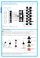
5.9 Connecting to the ZL180 control panel Motor terminals M -N Connecting the motor N ZL19 F -Fa Opening endstop microswitch R -Rc Closing-speed brake microswitch 6 Safety instructions Important safety instructions This product must only be employed for its originally intended use. Any other use is wrong and potentially dangerous. The manufacturer cannot be held liable for any damages resulting from wrongful, erroneous or negligent uses.
7 Maintenance Periodic maintenance to be carried out by the end-user is as follows: wipe clean the glass surface of the photocells; check that the safety devices work properly; remove any obstructions. We suggest checking the state of lubrication and tightness of the anchoring screws on the operator. To check the efficiency of the safety devices, move an object in front of the photocells when gate is closing. If the operator inverts the motion or stops, the photocells are working properly.
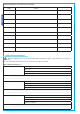
Periodic maintenance log for end-user (every 6 moths) Notes Signature 7.3 Extra-ordinary maintenance The following table serves to note down any extraordinary maintenance, repairs or improvements performed by specialised firms. N.B.: Any extraordinary maintenance must be performed by specialised technicians.
Installer’s stamp Operator name Date of job Technician’s signature Requester’s signature Installer’s stamp ENGLISH Job performed_____________________________________________________________________________________ ________________________________________________________________________________________________ Operator name The data and information shown in this manual may be changed by CAME cancelli automatici s.p.a. at any time without prior warning.
CAME UNITED KINGDOM LTD UNIT 3, ORCHARD BUSINESS PARK TOWN STREET, SANDIACRE NOTTINGHAM - NG10 5BP - U.K. Tel - 0044 115 9210430 Cod. 119DU32 V. 0.