
Instruction Manual

4
ENGLISH
The data and information shown in this manual may be changed by CAME cancelli automatici s.p.a. at any time without prior warning.
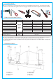
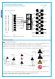
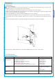
5.2 Tools and materials
Make sure you have all the tools and materials you will need for the installation at hand to work in total safety and complian-
ce with the current standards and regulations. The following figure illustrates the minimum equipment needed by the installer.
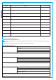
N.B.: If the cable length differs from that specifi ed in the table, then you must determine the proper cable diameter in the basis of
the actual power draw by the connected devices and depending on the standards specifi ed in CEI EN 60204-1.
For connections that require several, sequential loads, the sizes given on the table must be re-evaluated based on actual power
draw and distances.
5.3 Cable list and minimum thickness
Connections Type of cable Length of cable 1 < 10 m Leng. cable 10 < 20 m Leng. cable 20 < 30 m
Control panel power supply 230V 2F
FROR CEI
20-22
CEI EN
50267-2-1
3G x 1,5 mm
2
3G x 2,5 mm
2
3G x 4 mm
2
Flashing light 230V 2 x 0,5 mm
2
2 x 1 mm
2
2 x 1,5 mm
2
Photocell transmitters 2 x 0,5 mm
2
2 x 0.5 mm
2
2 x 0,5 mm
2
Photocell receivers 4 x 0,5 mm
2
4 x 0,5 mm
2
4 x 0,5 mm
2
24V Accessories power supply 2 x 0,5 mm
2
2 x 0,5 mm
2
2 x 1 mm
2
Command buttons 2 x 0,5 mm
2
2 x 0,5 mm
2
2 x 0,5 mm
2
Endstop 3 x 0,5 mm
2
3 x 1 mm
2
3 x 1,5 mm
2
Encoder plug 2402C 22AWG max. 30 m
Antenna connection RG58 max. 50 m
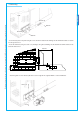
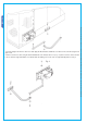
5.4 Standard installation
5 - Flashing light
6 - Selector switch
7 - Photocells
8 - Electric lock
1 - Operator
2 - Control panel
3 - Radio receiver
4 - Antenna