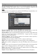
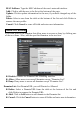
Routing This selection enables users to set how the WLAN Router forwards data: Static and Dynamic. Routing Table enables users to view the information created by the WLAN Router that displays the network interconnection topology. Static It enables users to set parameters by which the WLAN Router forwards data to its destination if the network has a static IP address. Network Address: Type the static IP address the network uses to access the Internet.
Dynamic This screen enables users to set the dynamic routing parameters. Transmit: Click the radio buttons to set the desired transmit parameters, Disabled, RIP 1, or RIP 2. Receive: Click the radio buttons to set the desired receive parameters, Disabled, RIP 1, or RIP 2.
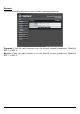
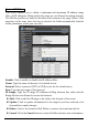
Routing Table This screen enables users to view the routing table of the WLAN Router. The routing table is a database created by the WLAN Router that displays the network interconnection topology. Network Address: Displays the network IP address of the connected node. Network Mask: Displays the network (subnet) mask of the connected node. Gateway Address: Displays the gateway address of the connected node. Interface: Displays whether the node is connected via a WAN or LAN.
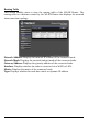
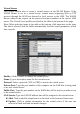
Access This page enables you to define access restrictions, set up protocol and IP filters, create virtual servers, define access for special applications such as games, and set firewall rules. Filters Using filters to deny or allow the users to access to the internet. Three types of filters can be select: MAC, Domain/URL blocking, and Protocol/IP filter. MAC Filters MAC Filter: Enables you to allow or deny accessing the internet. Disable: Disable the MAC filter function.
MAC Address: Type the MAC address of the user's network interface. Add: Click to add the user to the list at the bottom of the page. Update: Click to update information for the user, if you have changed any of the fields. Delete: Select a user from the table at the bottom of the list and click Delete to remove the user profile. Cancel: Click Cancel to erase all fields and enter new information.
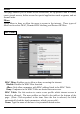
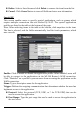
Protocol/IP Filters This screen enables you to define a minimum and maximum IP address range filter; all IP addresses falling within the range are not allowed accessing internet. The IP filter profiles are listed in the table at the bottom of the page. (Note: Click anywhere in the item. Once the line is selected, the fields automatically load the item's parameters, which you can edit.) Enable: Click to enable or disable the IP address filter. Name: Type the name of the user to be denied access.
Virtual Server This screen enables user to create a virtual server via the WLAN Router. If the WLAN Router is set as a virtual server, remote users requesting Web or FTP services through the WAN are directed to local servers in the LAN. The WLAN Router redirects the request via the protocol and port numbers to the correct LAN server. The Virtual Sever profiles are listed in the table at the bottom of the page. Note: When selecting items in the table at the bottom, click anywhere in the item.
Delete: Select a listed item and click Delete to remove the item from the list. Cancel: Click Cancel button to erase all fields and enter new information. Special AP This screen enables users to specify special applications, such as games which require multiple connections that are blocked by NAT. The special applications profiles are listed in the table at the bottom of the page. Note: When selecting items in the table at the bottom, click anywhere in the item.
Incoming: Defines which incoming communications users are permitted to connect with. Protocol: Select the protocol (TCP, UDP, or * for TCP+UDP) that can be used by the incoming communication. Port: Type the port number that can be used for the incoming communication. Add: Click to add the special application profile to the table at the bottom of the screen. Update: Click to update information for the special application if user have selected a list item and have made changes.
Firewall Settings This screen enables users to set up the firewall. The WLAN Router provides basic firewall functions, by filtering all the packets that enter the WLAN Router using a set of rules. The rules are listed in sequential order--the lower the rule number, the higher the priority the rule has. Enable: Click to enable or disable the firewall rule profile. Name: Type a descriptive name for the firewall rule profile. Action: Select whether to allow or deny packets that conform to the rule.
Update: Click to update information for the rule if the user has selected a listed item and has made changes. Delete: Select a listed item and click Delete button to remove the entry from the list. New: Click “New” to erase all fields and enter new information. Priority Up: Select a rule from the list and click “Priority Up” to increase the priority of the rule. Priority Down: Select a rule from the list and click “Priority Down” to decrease the priority of the rule.
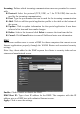
Management Management enables users to set up the Remote Management feature. Remote Management This screen enables users to set up remote management. Using remote management, the WLAN Router can be configured through the WAN via a Web browser. A user name and password are required to perform remote management. HTTP: Enables users to set up HTTP access of the Port number, and Remote IP Range for remote management.
Tools This page enables users to restart the system, save and load different settings as profiles, restore factory default settings, run a setup wizard to configure WLAN Router settings, upgrade the firmware, and ping remote IP addresses. Restart Click “Restart” to restart the system in the event the system is not performing correctly.
Settings This screen enables users to save settings as a profile and load profiles for different circumstances. User can also load the factory default settings, and run a setup wizard to configure the WLAN Router and Router interface. Save Settings: Click “Save” to save the current configuration as a profile that can load when necessary. Load Settings: Click “Browse” and go to the location of a stored profile. Click “Load” to load the profile's settings.
Firmware This screen enables users to keep the WLAN Router firmware up to date. Please follow the below instructions: Download the latest firmware from the manufacturer's Web site, and save it to disk. Click “Browse” and go to the location of the downloaded firmware file. Select the file and click “Upgrade” to update the firmware to the latest release. Ping Test The ping test enables users to determine whether an IP address or host is present on the Internet.
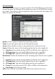
USB CONTROL CENTER UTILITY Utility The USB Control Center Utility is used to connect your computer to USB devices connected to the WLAN Router. The utility allows you to use USB devices as if they were connected directly to your PC through the Wireless N Home Router with USB port System Select this feature to completely close and exit from USB Control Center utility.
Auto-Connect Printer List Provides a list of installed printers on your computer. Select the printer you would like to add into the Auto-Connect Printer Lists. Configure Server Click this button to configure the USB server and to log into the user interface of the Wireless N Home Router with USB port. Print Sharing This section describes how to use a USB printer through the WLAN Router.
Set Auto-Connect Printer Provides a list of installed printers on your computer. Select the printer you would like to add into the Auto-Connect Printer Lists. Network Scanner This section describes the usage of a scanner through the Wireless N Gigabit Router with USB port. Once you click on the Network Scanner button on the USB utility the below image will appear.
Name: Type the name of the folder you would like to have the scanned images stored in. File Format: Select the file format Save Location: Click Browse and select the location where you would like to have the scanned files saved in. Back: Click to return to be previous screen. Next: Click to begin scanning Cancel: Click to cancel scanning job and to return to back to the USB Utility.
Connecting USB Storage Device This section describes the how to use the utility when connecting to USB storage device through the WLAN Router. Connect Click this button to establish connection to the selected USB device that is not configured to Auto-Connect, like USB storage devices. Disconnect Click this button to properly disconnect your computer form the connected USB device.
Note: Only a single user can establish connection to a USB device. Once the “Request to Connect” is approved, the connection to the USB device will automatically transfer to the requested user.
TECHNICAL SPECIFICATIONS Hardware Standards Wired: IEEE 802.3 (10Base-T), IEEE 802.3u (100Base-TX) Wireless: IEEE 802.11b, IEEE 802.11g, IEEE 802.11n (draft 2.0), IEEE 802.11e QoS USB 2.0 WAN 1 x 10/100Mbps Auto-MDIX port (Internet) LAN 4 x 10/100Mbps Auto-MDIX ports USB 1 x USB 2.0, 1.
LIMITED WARRANTY TRENDnet warrants its products against defects in material and workmanship, under normal use and service, for the following lengths of time from the date of purchase. 3 Years Warranty AC/DC Power Adapter, Cooling Fan, and Power Supply carry 1 year warranty.
Some TRENDnet products include software code written by third party developers. These codes are subject to the GNU General Public License ("GPL") or GNU Lesser General Public License ("LGPL"). Go to http://www.trendnet.com/gpl or http://www.trendnet.com Download section and look for the desired TRENDnet product to access to the GPL Code or LGPL Code. These codes are distributed WITHOUT WARRANTY and are subject to the copyrights of the developers. TRENDnet does not provide technical support for these codes.