
User Manual


16 17
ITALIANO
POLSKI
ESPAÑOL
FRANCAIS
FRANCAIS
FRANCAIS
FRANCAIS
FRANCAIS
DEUTSCH
ENGLISH
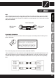
DMX CABLE:
NOTE:
• When fabricating your own cables, always observe the illustrations on this page. Never connect the shielding
of the cable to the ground contact of the plug, and always make certain that the shielding does not come into
contact with the housing of the XLR plug. If the shielding is connected to ground, this can lead to short-circuiting
and system malfunctions.
PLEASE NOTE: TERMINATION:
• With extended cable runs, the last device in the chain may require a terminating resistor in order to prevent
system malfunctions.
This is achieved by using a cable terminator module (Product No. K3DMXT3).
• Some manufacturers use 5-pole versions for data transmission instead of 3-pole XLR plugs. However, devices
with 5-pole XLR connectors can also be integrated in a DMX network with 3-pole XLR connectors. In this case,
a suitable cable adapter is required. The following illustration shows the correct pin-out of the corresponding
plugs.
Use of a terminating resistor (termination)
reduces interference and other problems during
signal transmission. It is always advisable to
connect a DMX termination module (resistance
120 ohms, 1/4 W) between pole 2 (DMX-) and
pole 3 (DMX+) of the last device in the chain.
Usual connection
DMX-512 output
3-pole XLR
DMX-512 input
3-pole XLR
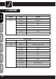
5-pole XLR(socket)
Pole 1: Ground
(shielding)
Pole 2: Signal (-)
Pole 3: Signal (+)
Pole 4: unused
Pole 5: unused
5-pole XLR(socket)
Pole 1: Ground
(shielding)
Pole 2: Signal (-)
Pole 3: Signal (+)
Pole 4: unused
Pole 5: unused
3-pole XLR(socket)
Pole 1: Ground
(shielding)
Pole 2: Signal (-)
Pole 3: Signal (+)
3-pole XLR(socket)
Pole 1: Ground
(shielding)
Pole 2: Signal (-)
Pole 3: Signal (+)