MSC-2769-SLD OWNER'S CAMERON MANUAL ASSEMBLY INSTRUCTION,CARE, MAINTENANCE & USER'S GUIDE ",,,",,, CAUTION This unit is designed to 8, with a maximum not to exceed to be used safely by up 6 children weight a combined of 100 pounds(45.4kgs) weight between the age of 2 each, simultaneously, of 600 pounds(272.72kgs). WARNING Please read this instruction manual before you start with the assembly or use this swing set.
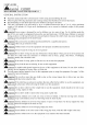
USER'S GUIDE 1 ]READ BEFORE [CAUTION! USING THIS I EQUIPMENT GENERAL INSTRUCTION • Read this manual • Observing • Recommending • This unit weight (272.72 and follow the following statements on-site is designed all instructions and warnings adult supervision to be used of 100 pounds (45.4 reduces for children safely kgs) using and assembling the likelihood of all ages by up to 6 children each, simultaneously, this unit. of serious fatal injury. at all times.
_WARNIN_ Instruct children not to get off equipment while it is in motion. Do not allow children to jump from moving play items. _WA_IN_ Parent to dress children appropriately while on and around this equipment include the use of well fitting shoes and the avoidance of ponchos, clothing t]1at is potentially hazardous while using equipment). _[_ WA_ING Do not allow children to climb or play on equipment scarves, jewelry when it is wet. Do not stand on the lawn swing when using this ride.
'_kWARNIN_ Instruct designed cables Lawn for use and chain swings, children with the not to attach equipment, as they my cause if applicable, items such to the as, but a strangulation are designed playground not limited equipment to, jump that ropes, are not clothesline, specifically pet leashes, hazard. for use by children two years of age and older.
IMPORTANT CONSUMER INFORMATION SHEET The Consumer Product Safety Commission estimates that about 100,000 playground equipmentrelated iniuries resulting from falls to the ground equipment treated annually in U.S. hospital emergency rooms. Iniuries involving this hazard pattern tend to be among the most serious of all playground iniuries, And have the potential to be fatal, particularly when the iniury is to the head.
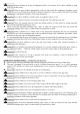
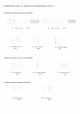
HARDWARE Hardware (ACTUAL SIZE BUT FOR REFERENCE ONLY ) used for main frame assembly ,:LB 1) BOLT • :<........................ i f 5/16"x63 4PCS _), BOLT 5/16"x63 12PCS /7 // \ \ / ) / \5 LBy NYLON NUT 5/16" 16PCS Hardware _ ARC WASHER 28PCS ,_ LARGE WASHER 4PCS used for swing seats assembly \ \ / / '/J2"_' ARC WASHER '\ // 4PCS /F-_\ i 2_ LARGE J6/ WASHER 4PCS k. ii .........
Bracket used for glide ride assembly \ / / _N_ BOLT 5/16"x25 2PCS @, NYLON NUT 5/16" 2PCS Hardware used for glide ride assembly _} BOLT /'i i\ 1/4"x34 ,<__ BOLT 4PCS 1/4"x48 2PCS Y, '.\.. _ ../ , _',_, BOLT 1/4"x34 ,@ 4PCS SCREW O5.
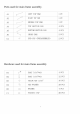
Hardware used for slide assembly f '\ (Z_ BOLT 1/4"x34 _gl BOLT 1/4"x59 14PC S _X BOLT 1/4"x96 j 2PCS 2PCS / \ \.
Tools needed for assembly Special Socket Wrench (included) Tape Measure Not included wrench (included) Hammer (If you intend to install anchor, this is needed.) Not included j .........................................................................................................................................................
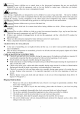
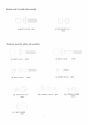
Parts used for main frame assembly. A1 A2 A3 _::::_:_:_:'_ _ ....-s_::::_" LEFT TOP BAR 1 PC RIGHTTOP BAR 1 PC MIDDLE TOP BAR 1 PC A4 _ TOP SECTION LEG 4 PCS A5 _ BOTTOMSECTION LEG 4 PCS A6 %_ CROSS BAR 2 PCS END CAP (PREASSEMBLED) 2 PCS C2 5_ Hardware used for main frame assembly B1 BOLT 5/16".
Parts used for swing seats assembly Jl PVCCOVERED CHAIN(PREASSEMBLED) 4 PCS EYE BOLT WITH ATTACHMENT BOLT (PREASSEMBLED) 4 PCS EYE BOLT (PREASSEMBLED) 4 PCS K1 SWINGSEAT 2 PCS K2 RUBBERCOVER (PREASSEMBLED) 4 PCS J3 J4 ___ ,,9 N Hardware used for swing seats assembly J2 ARC WASHER 4 PCS J5 LARGE WASHER 4 PCS J6 NYLONNUT 5/16" 8 PCS K3 PLASTIC CAP 8 PCS Parts used for trapeze assembly P1 TRAPEZE TUBE 1 PC $1 EYE BOLT WITH ATTACHMENTBOLT 2 PCS T3 RUBBER CAP (PREASSEMBLED)
Parts used for glide ride assembly L1 TOP SECTION HANGER 2 PCS L2 ..................................... BOTTOMSECTION HANGER 2 PCS L3 .......................................
Hardware used for glide ride assembly N1 _ BOLT 1/4"'34 4 PCS N2 _:_ BOLT 1/4"'48 2 PCS N4 i BOLT 1/4_,34 4 PCS N5 ii SCREWs5.5.16 4 PCS N6 J-BOLT 2 PCS N8 NYLONNUT 1/4" 10 PCS N9 CAP BOLT 1/4".
Parts used for slide assembly Xl SLIDE SUPPORT(W/ATTACH-MENTHOLE TO I,EG) 1 PC X2 SLIDE SUPPORT 1 PC X3 SLIDE LEG TUBE 2 PCS X4 SLIDE TOP SUPPORT BAR 1 PC X5 SLIDE FRONT SUPPORT 1 PC X6 SLIDE LADDER STEPS 3 PCS Y2 SLIDE 1 PC Y3 CAP FOR X4(PREASSEMBLED) 2 PCS Hardware used for slide assembly 1 3
ASSEMBLY INSTRUCTION Place the playground equipment on level ground, not less than 6 ft (1.8 m) from any structure or obstruction such as a fence, garage, house, overhanging branches, laundry lines, or electrical wires. Do not install the playground equipment over concrete, asphalt, packed earth, or any other hard surface. A fall onto a hard surface can result in serious injury to the user.
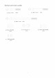
Step 1 Insert A1 into A3, secure with B1, B3, B4 and C1. Insert A3 into the other end of A2, secure with B1, B3, B4 and C1 Note: Please make sure that concave holes face down and round holes face up. Concave hole faces down Round hole faces up Cl A2 B4 B1 A1 B1 Cl A1 Step 2 Insert small end of A4 into the socket at the end of A1. B2 B4 C1 2 B4 B2 -L Align the holes and secure using B2, B4, B3 and C 1. / / // J // A4 / / B3 B4 Insert small end of A4 into the socket at the end of A2.
Step 3 Insert A5 into A4 and align the holes. Attach A6 to the left outer side of A5. > Secure all three pieces using B2, B4, B5,B3 and C 1. Repeat above the right side. B2 B5 B4 B4 B2 A6 B4 Cl /// B3 A5 \, \ AS \\ _\,, \\, \ \\ \, \ \, ',, \ A1 K3 J6 Step 4 J2 J3 K2 Insert J3 which is pre-assembled J1, K2 and J4 into holes on A1. with Secure it with J2, J6 and K3. Repeat for remaining two chains on A1.
Step 5 > AttachK1 to J4. Secure with J5,J6 and K3. Repeat for remaining One swing seat. j1 J4 j1 j4 [ / i / / J5 J6 J5 K3 J6 K3 Step 6 ;_ Attach P1 to S1. Attach S 1 to A3. Secure using $5, T4 $6 and $6 T4.
N3 Step 7 Attach L4, L5 and L6 to A2 as shown. Secure using N3 and N7. L6 L6 , Use special socket wrench and screw driver to tighten. // USE SPECIALSOCKET WRENCH ANDSCREW DRIVERTO TIGHTENNT. M1 Step 8 Attach M5 to L2. M2 Secure using N5. Attach L2 to L 1 and align holes. L1 Secure using N4, N10 and N8. N10 Insert M 1 into L 1 if not pre-assembled. Attach M 1 to the top of L 1 and insert M2 into M1 and align if not pre-assembled.
N8 NIO L5 N2 Step 9 L1 Attach L1 to L5. _i N2 Secure using N2, N10 and N8. L1 [d [ i ii ii ii ii ii ii ii ii ii ii ii ii k_ [ i ii ii ii ii ./ ./ Step 10 Insert M3 into L2 if not pre-assembled. Attach L3 to outer sidesof L2. L1 SecureusingN6 and N9. Seediagram for sequence.
N1 Step 11 Attach M4 to L3. r Secure using N1,N10 and N8. N1 L3 N10 M4 J N8 7_1 Z7 Z5 / / Zl / //¸ // // i/ // // //A6 Step 12 X8 / Attach X8 to A6 as shown. /' Xl Zl _- Attach Z1, X7,Y1,Z7 to X8 and secure with Z5. Do not over-tighten Z5 to allow room for adjustment. Zl ' // A5 ///,.... Attach X1 to X7. A5 Secure using Z1 and Z5.
Y3 Bolthole facesup Y2 X4 Step 13 Y3 Attach X5 to Y2. Secureusing Z1 and Z4. Z4 Zl Attach X4 to Y2. Note: make sure the bolt holes face up. Insert Y3 into X4 if not pre-assembled. Z1 Z4 ',, • J j-J _ J ............... -...... _J Narrow side Direction as shown - X5 \ "-. below) _ \ \ \\, Step 14 Attach X6 to X 1 and X2. Wide side faces the front ', direction of the slide / / / \\\\\ _- Secure each side using Z 1,Z7and Z5. _- Attach X3 to X 1 and X2.
X2 Z2 \Z6 X4 Step 15 Z2 Z6 Z6 Attach slide assembly from Step 13 to X1 and X2. Z5 Y2 Secure using Z2, Z6, Z7, and Z5 as shown. Xl Insert Z3 into Z6 and inset into Xl, X2 and X3 as shown. X3 Secure with Z4 and Z5. You have finished assembling your playground equipment. Now go back and securely tighten all nuts and bolts before equipment. NOTE: Do not let children anchored.
OPTIONAL ANCHORS (NOTE: ANCHORS ARE NOT INCLUDED, SOLD SEPARATELY) By anchoring your set with Ground Anchors, you will be able to move your gym set at a future date. Either method is suitable for hard soil (clay, etc.). If your soil is soft (sand, etc.), the corkscrew method is recommended. If you wish to permanently secure your gym set, either type of anchor may set in concrete. Ensure equipment is firmly anchored (cementing is usually recommended).
FRAME LEG "xx xx" • / /, x 4b I // db I 4 4b .
MANUFACTURER'S SPORTSPOWER LTD. warrants LIMITED its GYM products WARRANTY for (180) days against defects in material, workmanship and rust painted parts which compromises the structural integrity of the product when used for the purpose intended, normal conditions, and provided it receives proper care and maintenance. Surface rust is not covered under warranty. This warranty coverage non-transferable.