C8 Rotavator with PowerSafe® Clutch Operating Instructions Before commissioning the machine, read operating instructions and observe warning and safety instructions.
C8 Rotavator Contents Page 3 Safety Page 4 Controls Diagram & Description Page 5 Assembly Instructions Page 6 How to Start Engine Operation How to Stop Engine Page 7 Operating Hints Page 8 Replacing the Tines Page 9 Rotavator Sticker Positions Adjusting the Rotavator Width Page 10 Maintenance Guide Page 11 Maintenance Programme Page 12 Service Information Page 14 Troubleshooting Guide Page 15 Risk Assessment Page 16 Service Record Page 18 Warranty Registration Page 19
C8 Rotavator Safety ALWAYS start the engine in the open air DO NOT smoke when refuelling DO NOT mix OIL with the fuel ALWAYS stop the engine before making any adjustments, refuelling, moving or cleaning, or when the unit is unattended USE ONLY fuel from containers designed for this purpose - refuel outdoors only and replace the tank cap securely IN CASE of petrol spillage move the machine away from the area of spillage and allow the petrol vapours to dissipate before starting the engine DO NOT remove any s
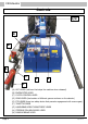
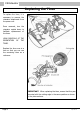
C8 Rotavator Controls G/H N B A F D E C (A) OPC LEVER (red lever that stops the machine when released) (B) ENGINE STOP LEVER (C) CLUTCH CONTROL LEVER (D) GEAR LEVER (the location of different gears are shown on the selector) (E) PTO LEVER (there is a safety device that prevents engagement with reverse gear) (F) THROTTLE LEVER (G) HANDLEBAR HEIGHT ADJUSTMENT LEVER (H) STEERING COLUMN SWIVEL LEVER (N) PARKING BRAKE LEVER Page 4 C8/0914
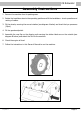
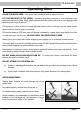
C8 Rotavator Assembly Instructions 1. Remove the machine from its packing case. 2. Rotate the handlebar stem to the operating position and fit the handlebars - check operation and routing of cables. 3. Fit the wheels, ensuring the correct rotation (see diagram A below) and check the tyre pressures (20psi). 4. Fit the gearbox dipstick. 5. Assemble the rear flap on the digging unit ensuring the sticker labels are on the outside (see diagram B below) and attach the unit to the machine. 6.
C8 Rotavator To Start Engine Using the dipstick provided, check the engine oil level. Top up with 10w/40 oil if necessary. Check fuel level. Only use unleaded petrol from a clean container. Never re-fuel when the engine is hot or running. Leave 1” air space in the fuel tank. Turn the fuel tap to ‘ON’ position, if the engine is cold set the choke lever to ‘ON’ position. Before starting the engine ensure the gear lever (D) is in neutral position and the power take-off (PTO) lever is disengaged (E).
C8 Rotavator Operating Hints CLEAR THE WORK AREA. Long grass must be cleared and all debris removed. LET THE MACHINE DO THE WORK. Excessive downward pressure on the handlebars may cause the machine to jump. Apply gentle pressure and the machine will find its own digging depth according to the type of ground. If the ground is hard, position the depth adjuster centre knife on the top hole and make several passes until the desired depth is achieved.
C8 Rotavator Replacing the Tines To replace the tines, it is necessary to remove the rotavator attachment from the power unit. Once removed, turn the rotavator upside down to facilitate replacement of the tines. LOOK CAREFULLY AT THE ORIENTATION OF THE TINES. Replace the tines one at a time so that you can use the remaining tines as a reference. IMPORTANT: When replacing the tines, ensure that they are mounted with the cutting edge in the same position as shown in the picture above.
C8 Rotavator Adjusting Rotavator Width The rotavator width can be adjusted using the following configurations: Current unit No of Tines No of Flanges Increase or Decrease New No of configuration Tines No of Flanges 52cm (20”) 16 4 Increase 66cm (26”) 20 6 66cm (26”) 20 6 Decrease 52cm (20”) 16 4 PLEASE NOTE: The 46cm rotavator attachment (12 tines on 4 flanges) cannot be adjusted in size 52cm (20”) - 16 tines on 4 flanges 66cm (26”) - 20 tines on 6 flanges Rotavator Sticker Position
C8 Rotavator Maintenance Guide For engine maintenance please refer to engine manufacturers manual. After every hour of operation stop the engine and remove the spark plug cap. Check engine oil level (recommended oil SAE 10w/40). Before checking the oil level ensure the machine is level. Remove all foreign matter from the digging knives assembly e.g. wire, string, grass etc.
C8 Rotavator Maintenance Programme OPERATION ENGINE Check engine oil level 10w/40 See separate engine manual GEARBOX Check gearbox oil level (see page 13) & CONTROLS Check nuts & bolts EVERY DAY EVERY WEEK X X X X X X Ensure clutch cable has free play X Check tyre pressure (20psi) X Lubricate control cable/linkages X Check control cable operation X Check operation of safety devices X EVERY YEAR or 100 HOURS X Change gearbox oil (see page 13) DIGGING UNIT Grease gear speed detent bal
C8 Rotavator Service Information Every Week • With the machine on a level surface, check the gearbox oil level, top up as necessary using the correct oil as listed below. The gearbox oil level should reach between the two notches on the dipstick (fig. 2, C). After the First 2 Weeks or 30 Hours of Work • Replace the gearbox oil filter ONLY, (fig. 1, A), part number 58056249. • Check the gearbox oil level using the dipstick (figs.
C8 Rotavator Service Information Gearbox Oil Quantities CAMON C8 = approx 2.3 litres Oil Type Fuchs Titan Hyp 90 Valvoline 80w-90 GL-5 Morris EP80w/90 API GL5 Castrol EPX 80w-90 Motorex Hypoid SAE 80w/90 API GL5 Millers Hypoid 80w90 GL5 Comma EP80w-90 GL5 Agip Rotra MP 80w-90 Rock Oil SD API GL5 80w/90 Alternatively any oil meeting API GL-5 80w/90 specification may be used. Multigrade engine oil must NOT be used. Fig. 2 C C8/0914 B Fig.
C8 Rotavator Troubleshooting Guide PROBLEM POSSIBLE CAUSE REMEDY Unable to select gear Pressure washing has removed lubrication of gear lever detent ball. Grease the detent ball and quadrant. Unable to pull engine over Machine has been tipped on side for cleaning and engine oil has filled the cylinder bore causing a hydraulic lock. Remove spark plug and air filter. Stand to one side and pull over engine to clean out oil. Change engine oil and air filter. Clean spark plug.
C8 Rotavator Risk Assessment HAZARDS RISK LEVEL General ACTION NEEDED The machine should only be used by trained operators. Machine tipping over Low Do not use on slopes over 25o. Machine jumping High Ensure the centre knife is in good condition and adjusted to suit the ground conditions. Use the depth adjuster located on top of the rotavator to adjust the centre knife. NEVER apply excessive downwards pressure on the handlebars.
C8 Rotavator Service Record To ensure your machine is kept in peak condition, we recommend that you have it serviced regularly by one of Tracmaster’s Authorised Agents. To find out who your local Authorised Agent is, contact Tracmaster on 01444 247689.
C8 Rotavator Register your warranty online now! www.tracmaster.co.uk • Complete the online warranty form. • View and download spare parts diagrams. • View and download owners manuals and operating instructions. • See working video clips of machines from our BCS and CAMON ranges.
C8 Rotavator Warranty Registration To validate your warranty please complete the form below and return it to: Tracmaster Ltd, Sovereign Centre, Victoria Road, Burgess Hill, RH15 9LR Alternatively visit www.tracmaster.co.uk and complete the online form. CUSTOMER DETAILS Name: .................................................................................................... Company (if applicable): ....................................................................................................
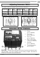
C8 Rotavator Machine Overview Diagram Engine stop lever Parking brake lever OPC lever Throttle lever Clutch lever Wheel speed lever Digging knives engagement lever Handlebar adjuster Gearbox oil level Engine oil level Petrol cap Choke lever Fuel tap Recoil starter Vibration & Sound Levels MACHINE RPM VIBRATION M/SEC2 (3 AXIS) SOUND LEVEL dB(A) CAMON C8 Rotavator 3100 2.9 85.
© Tracmaster Ltd 2014. Specifications are subject to change without prior notice. C8/OPM/0914 Tracmaster Ltd, Sovereign Centre, Victoria Road, Burgess Hill RH15 9LR T: +44 (0) 1444 247689 F: +44 (0) 1444 871612 W: www.tracmaster.co.uk E: info@tracmaster.co.