OWNER’S MANUAL PW MOTORIZED 7” WIDE TFT LCD COLOR MONITOR CNT-701
ANY CHANGES OR MODIFICATIONS IN CONSTRUCTION OF THIS UNIT DEVICE WHICH IS NOT APPROVED BY THE PARTY RESPONSIBLE FOR COMPLIACE COULD VOID THE USER’S AUTHORITY TO OPERATE THE EQUIPMENT.
WARNING The WARNING mark is intended to alert the user to the important operating instructions. Wrong operations will result in severe injury to the unit. DO NOT WATCH MONITOR WHILE DRIVING Watching the video while driving may interrupt driving and may cause an accident. DO NOT OPERATE ANY FUNCTION THAT TAKE YOUR ATTENTION AWAY FROM DRIVING YOUR VEHICLE Operation of some functions for this unit is very complicated. It is necessary to put these functions in to a special MENU screen.
Contents CONTENTS GETTING STARTED …………………………………………………………… ……………………………………………………………… FEATURES …………………………………………………………… ACCESSORIES …………………………………………………………… CONNECTION …………………………………………………………… INSTALLATION ………………………………………………………………… MONITOR …………………………………………………… REMOTE CONTROL 5 5 5 6 6 7 8 BASIC OPERATION …………………………………………………………… 9 ……………………………………………………… 9 POWER ON / OFF ……………………………………………… 9 OPENING THE MONITOR ……………………………………………… 9 CLOSING THE MONITOR …………………………………………… 9 ADJUSTING TILT POSITION …………………………………………
Getting Started FEATURES 7" wide high resolution TFT active matrix display Slim size (1/2 DIN) design NTSC/PAL compatible Built-in FM transmitter 2 Video input / 1 Video output ACCESSORIES 2. Remote control & Lithium battery CR2025 1. Speaker SPK-L A/M SC SPK-R CH M CH MENU VOL AN + VOL - CH M CH MODE MUTE OPEN NAVI ASPECT C A IN TILT OUT 3.
Getting Started Connection GPS RS-232/TMC YELLOW RED To AUDIO OUTPUT (R) BLACK To AUDIO OUTPUT (L) RED WHITE YELLOW To VIDEO OUTPUT YELLOW To REAR VIEW CAMERA VIDEO INPUT RED WHITE YELLOW AVIN-R To AUDIO INPUT (R) AVIN-L To AUDIO INPUT (L) AVIN-V To VIDEO INPUT PINK - ILLUMINATION SPK-L ORANGE - REVERSE GEAR SENS BROWN - REVERSE GEAR SENS SPK-R Installation PW PW
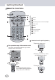
Getting Started MONITOR PW 8 Function No.
Getting Started REMOTE CONTROL DE MO CH MENU VOL M UT E VOL Power Mode Volume Up / Down , Cursor Left / Right SC AN CH FO IN Tilt In / Out Mute Menu 1 2 3 4 5 6 A IN TILT OUT Cusor Up / Down Tilt Up / Down Open UP OPEN TILT DN Remote Control replacing battery 1 Opening the battery cover. The operation range of the remote control The remote control will work within the range of about 30 degrees and 3 meter distances. PUSH PULL OUT 2 Replacing a new battery as shown.
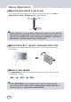
Basic Operation POWER ON / OFF 1. POWER ON Press any button on the unit or Power Button of the remote control to turn the power on. The monitor is automatically opened. When REVERSE wire is connected to the signal output (12V) of the reverse gear, the monitor is automatically opened and the mode is set to RVC 2. POWER OFF Press the Power Button on the unit more than 1 second or the remote controller again to turn the power off. And the monitor is automatically closed.
Basic Operation ADJUSTING MOVE POSITION The move position can be adjusted in 4 steps by pressing more than 2 sec Tilt Up / Down Button or Tilt In / Out Button of the remote controller. 7mm 7mm If the monitor is not parallel to the front of the unit, the MOVE function is not operated. You can hear fast beep tone, when you operate the mechanism under abnormal conditions (Minimum, Maximum, crooked angle of the front panel).
Basic Operation SETTING THE CAMERA IN When you install a rear view camera, you must connect a rear view camera to RVC. If you put the gear lever to R (Reverse) to move your car backward, the rear view camera video will be displayed on the screen through the RVC mode. WARNING SCREEN The monitor shows the following warning picture when parking brake is not pulled or while driving to prevent traffic accident that may happen while watching the screen.
Function SELECTING THE MENU You can select the menu to make this unit or VIDEO sources connected to this unit in the best conditions. 1. Press Menu Button to select desired menu. Each time you press Menu Button, the menu changes as follows. PICTURE AUDIO SETTING MENU OFF 2. Press Cursor Up / Down Button to select the item that you want to adjust. The background color of the selected item changes to yellow. 3. Press Cursor Left / Right Button to adjust the selected item.
Function 7. SCREEN FLIP : Each time you press SCREEN FLIP button, screen display will be changed flip mode and normal mode. The FLIP screen will be useful when this unit is installed in reversed mode as follows (FLIP mode: 180° rotated image) PW For memorizing re-adjusting value, press Menu Button and exit PICTURE page. AUDIO CONTROL Press Menu Button repeatedly to show TV & AUDIO on the screen. Press Cursor Up / Down Button to select the desired item.
Function MENU SETTING CONTROL Press Menu Button repeatedly to show MENU SETTING on the screen. Press Cursor Up / Down Button to select the desired item. Press Cursor Left / Right Button to change the item’s value or level. 1. TV SYSTEM : TV output type select (AUTO, PAL, NTSC) 2. DISPLAY MODE : The picture is shown as 4:3 or 16:9 sized screen. 3. OSD TIMEOUT : The OSD TIMEOUT can be adjusted from 5SEC ~ No time out. “00” value is no time out. The default set is 10 seconds. 4.
GENERAL Power does not turn on. (No sound is produced) ● Fuse is blown ● Replace with a fuse of the same amperage. If the fuse blow again, consult installation shop where you purchased it from. ● Incorrect wiring ● Consult installation shop where you purchased it from. Nothing happens when buttons are pressed. Display is not accurate. The microprocessor has malfunctioned due to noise, etc. Power it off and power it on again.
GENERAL Power Supply Power Consumption Operating Temperature Video Input signal Video output signal Dimension (W × H × D) Polarity Weight Net Gross DC 14V ( 11V ~ 15V ) 1.5 A -10℃ ~ +60℃ 1.0 Vpp / 75Ω 1.0 Vpp / 75Ω 178 × 25 × 189 mm Negative Ground 1.7Kg 2.