MANUALE D’INSTALLAZIONE INSTALLATION MANUAL MANUEL D'INSTALLATION 取付マニュアル INSTALLATIONSANLEITUNG MANUAL DE INSTALACION Per l’utilizzo dell’ErgoBrain fate riferimento al Manuale d’uso Please refer to the Operating Manual for how to operate the ErgoBrain Pour l'utilisation d'ErgoBrain, consulter le Manuel d'Instructions エルゴブレインの操作に関しては操作マニュアルをご覧ください。 Für den Gebrauch des ErgoBrain verweisen wir auf die Bedienungsanleitung Para utilizar el ErgoBrain, tomar como referencia el Manual de Uso Rev. 2.
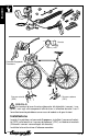
ITALIANO Basetta Comando Ergopower: Trasduttore Sensore velocità (SPD) Sensore cadenza (CDC) PERICOLO! Assicuratevi di aver fissato saldamente alla bicicletta i sensori, i magneti, i cavi e gli altri componenti affinché non si allentino durante l’uso. Il loro allentamento potrebbe essere causa di cadute e di gravi lesioni.
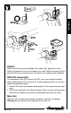
Trasduttori Inserto in resina Trasduttore Anello rotante OK NO! Pulsante Trasduttore Nota: Fate attenzione a non perdere i pezzi di dimensione molto ridotta forniti nella confezione. Nota: Alcuni pezzi sono realizzati appositamente per essere montati a destra o a sinistra, fate attenzione a non montarli invertiti. PERICOLO! Tenete tutti i pezzi lontani dalla portata dei bambini. 1. Portate il comando nella posizione di pignone più piccolo. 2.
ITALIANO SPD SENSOR 10 cm 5 mm CDC 5 mm Sensori e Magneti di velocità (SPD) e cadenza (CDC) • Posizionate i sensori in modo che la loro distanza dai magneti sia inferiore ai 5mm e che il centro del magnete durante la rotazione sia allineato con la linea di riferimento sul sensore. Importante: posizionate il magnete ed il sensore ad una distanza massima di 10 cm dal perno del mozzo. Fissate il sensore di velocità (SPD) alla forcella anteriore destra.
ITALIANO SPD CS CDC Basetta Fissate il supporto a fianco dell’attacco manubrio (alla sua destra). Stringete la vite. Fissate la basetta sul supporto e stringete la vite. Regolate la posizione e l’inclinazione del supporto in modo che l’unità centrale sia allineata al manubrio. Cavi di collegamento dei sensori di velocità e cadenza I connettori per il collegamento dei sensori di velocità e cadenza si trovano sulla basetta.
ENGLISH bracket Ergopower lever: Interface sensor SPD sensor CDC sensor DANGER! Be sure to attach all sensors, magnets, wires, and other hardware securely to the bicycle so they will not become loose when riding. If they become loose, they could cause you to fall from the bicycle, resulting in serious personal injury. How to Install Insert the interface sensor into your Ergopower lever, attach the SPD sensor to your front fork and the CDC sensor* to your chainstay.
are connected to the bracket.) Then install the bracket to the center of your handlebar. If your bicycle already has the Ergopower levers, you need to detach them according to the instruction. *) Whether to install the CDC sensor or not, is your choice. Resin cover Interface sensor Rotary-ring OK NO! Button Interface sensor Note: Tiny parts are included. Be careful not to lose them. Note: Some parts are specified for right side and left side. Be careful not to install them in the reverse way.
SPD ENGLISH SENSOR Within 10 cm 5 mm CDC 5 mm SPD Sensor and Magnet / CDC Sensor and Magnet • Install the sensors so that the clearance between the sensors and their magnets become less than 5mm, and that the center of the magnets and their sensors' marking lines align when rotating the wheel. Important: attach the sensor and the magnet within 10cm from the hub axle. Attach the SPD sensor to the right front fork. Attach the SPD magnet to the spoke of the front wheel.
ENGLISH SPD CS CDC Bracket Attach the arm next to the handlebar stem (right side). Tighten the screw. Attach the bracket to the arm and tighten the screw. Adjust the angle and the position of the arm so that the main unit comes to the center of the handlebar. SPD/CDC Sensor Wire The connectors of the SPD sensor and CDC sensor are inside the bracket. When detaching the CDC sensor wire, or when replacing either of the wires, follow the procedures below: 1. Remove the screw at the bottom of the bracket.
FRANÇAIS Base Poignée Ergopower: Transducteur Senseur vitesse (SPD) Senseur cadence (CDC) DANGER! Assurez-vous de bien fixer les senseurs, les aimants, les câbles et les autres composants au vélo afin d’éviter tout relâchement durant l’utilisation. Leur relâchement ou bien leur détachement pourrait causer des accidents et des graves blessures.
Si les poignées Ergopower sont déjà montées sur votre vélo, il est nécessaire de les enlever du cintre (lisez le mode d’emploi des poignées Ergopower). *) C’est à vous de décider d’installer ou pas le senseur de cadence (CDC). Transducteurs Levée du transducteur Inserez les touches comme de déssin. F -3 Enlevez avec soin le transducteur et poussez sur la touche vers l'interieur de la poignée. FRANÇAIS Note: Prenez soin de ne pas perdre les petites pièces qui se trouvent dans l’emballage.
SPD SENSOR FRANÇAIS Maximum 10cm 5 mm CDC 5 mm Senseurs et Aimants de la vitesse (SPD) et de la cadence (CDC) • Positionnez les senseurs de façon à ce que la distance entre les deux aimants soit inférieure à 5mm et que le centre de l’aimant durant la rotation soit aligné avec la ligne de référence du senseur. Important: positionnez l’aimant et le senseur á une distance maximum de 10 cm de l’axe du moyeu. Fixez le senseur de vitesse (SPD) au forreau droit de la fourche.
CS CDC Base Fixez le support à côté de la potence (côté droit). Serrez la vis. Fixez la base au support et serrez la vis. Réglez la position et l’inclinaison du support de façon à ce que l’unité centrale soit horizontale sur le cintre. Câbles de connexion des senseurs de vitesse et de cadence Les connecteurs pour la connexion des senseurs de vitesse et cadence se trouvent sur la base. Pour déconnecter le câble du senseur de cadence ou pour remplacer l’un des câbles suivez les instructions ci-après: 1.
JAPANESE ブラケット エルゴパワーレバー: インターフェイスセンサー スピードセンサー ケイデンスセンサー センサー・マグネット・ワイヤー・その他の部品は走行中にゆるむこと が無いように自転車にしっかりと取付けてください。不確実な取付けは 危 険 部品の落下等による事故につながる恐れがあり危険です。 取付説明書 エルゴブレインを使用するにはエルゴパワーレバーにはインターフェイスセンサーを、 フロン トホークにスピードセンサー、 チェーンステーにケイデンスセンサーの装着が必要です。 それ ぞれのセンサーはブラケットに接続されています。 ブラケットをハンドルの中央に取付てエル J -2
ゴブレインを装着します。 すでにエルゴパワーレバーが取付けられているとき はこの説明に従って一旦外す必要があります。 ケイデンスセンサーは装着・非装着を選択できま す。 インターフェイスセンサーの取付 重要:小さな部品が含まれます。 なくさないよう慎 重に作業してください。 パーツには右用・左用がありますので間違 えないでください。 注 意 子供の手の届くところへ置かないでくださ い。 1. エルゴパワーレバーのシフトレバーを操作し、 ギア位置を落としきります。 スペーサー 2. 5mmの六角レンチでエルゴパワーレバーを外 します。 インターフェイスセンサー 4. インターフェイスセンサーの左右を間違えない ように回転リングの位置を図のように合わせ、 回転リング 座部に組み込みます。 重要:インターフェイスセンサーの回転リン OK NO! ボタン グは黒が左用です。白 (9 s) または赤 (1 0s) が右用です。 5.
SPD SENSOR 10cm以内 5 mm JAPANESE CDC 5 mm SPDセンサー/マグネット・CDCセンサー/マグネットの取付 どちらのセンサーもマグネットとの距離が5ミリ以内でマグネットがセンサーの指示線を 通過する位置になるよう調整します。 重要: センサー・マグネット位置はハブ軸から10cm以内に取付てください。 スピードセンサーを図のように右側フロントホークに取付けます。 スピードマグネットを前輪スポークに取付けます。 ケイデンスセンサーは左側チェーンステーに取付けます。 マグネットは左側クランクの ペダルシャフトの窪みにはめ込みます。窪みがほとんど無いときはカバー付マグネット をクランク内側に貼付、ナイロンタイで補強します。 重要:センサー・マグネットは走行中ゆるまないようにしっかりと固定してください。 J -4
SPD CS ブラケットの取付け ステムの右側にアームをはめネジで固定します。 アームにブラケットをネジ止めします。ハンドル中央にメインユニットがつくよう にアームの位置・角度を調整します。 SPD/CDCセンサーコードの接続 ブラケットにはSPDセンサー・CDCセンサーのコネクターが接続されています。 CDCセンサーを外すときやコードが切れてセンサーを交換するときは次の手順 で行います。 1. ブラケット下部にあるネジを外し、 コネクターカバーを取ります。 2.
Montageeinheit DEUTSCH Ergopower-Hebel: Transduktor Geschwindigkeitsfühler (SPD) Trittfrequenzsensor (CDC) ACHTUNG, GEFAHR! Stellen Sie sicher, dass Sie Sensor, Magnete, Kabel und die anderen Komponenten gut am Rad befestigt haben, da sie sich beim Fahren keinesfalls lösen dürfen. Falls sie sich lösen, können Stürze und schweren Verletzungen die Folge sein.
diese vom Lenker abnehmen (hierzu verweisen wir auf die Montageanleitung für die Ergopower-Hebel). *) Sie können selbst bestimmen, ob Sie den Trittfrequenzsensor (CDC) installieren wollen oder nicht. Transduktoren Kunstharzeinsatz Transduktor Drehring NO! Druckknopf Transduktor Abnehmen des Transduktors Die Druckknöpfe so wie dargestellt einsetzen D -3 Nehmen Sie den Transduktor vorsichtig ab und drücken Sie den Druckknopf zur Innenseite des Schalthebels hin.
SPD SENSOR Maximum: 10 cm. 5 mm CDC DEUTSCH 5 mm Sensor und Magnete für Geschwindigkeit (SPD) und Trittfrequenz (CDC) • Positionieren Sie die Sensoren so, dass ihr Abstand von den Magneten weniger als 5 mm beträgt und dass das Zentrum des Magneten bei der Drehung auf die Bezugskerbe am Sensor ausgerichtet ist. Wichtig: Bei der Montage des Computers Ergobrain 9 S den Magnet und den Sensor in einer maximalen Entfernung von 10 cm von der Nabenachse positionieren.
SPD CS CDC Montageeinheit Verbindungskabel von Geschwindigkeitsfühler und Trittfrequenzsensor Die Verbinder zum Anschließen von Geschwindigkeitsfühler und Trittfrequenzsensor befinden sich an der Montageeinheit. Soll das Trittfrequenzsensorkabel abgenommen oder eines der Kabel ersetzt werden, so ist folgendermaßen vorzugehen: 1. Lösen Sie die Schraube unten an der Montageeinheit und nehmen Sie die Verbinderabdeckung ab. 2. Ziehen Sie den Verbinder heraus.
Base ESPAÑOL Maneta Ergopower: Transductor Sensor velocidad (SPD) Sensor cadencia (CDC) PELIGRO! Asegurarse de fijar adecuadamente a la bicicleta los sensores, los imanes, los cables y el resto de componentes para que no se aflojen durante su utilización. Su desprendimiento puede ser causa de caida y graves lesiones.
Instalar la base en el centro del manillar. Si las manetas Ergopower han sido ya montadas en vuestra bicicleta debéis desmontarlos del manillar (consultar las instrucciones de los mandos Ergopower). *) Podéis decidir si instalar o no el sensor de la cadencia (CDC). Transductores Inserto de resina Transductor Anillo rotante OK NO! Pulsante Desmontaje del transductor Introducir los pulsantes como ilustrado E -3 Desmontar con cuidado el transductor y apretar el pulsante hacia el interior del mando.
SPD SENSOR 10 cm 5 mm CDC 5 mm ESPAÑOL Sensores y Imanes de velocidad (SPD) y cadencia (CDC) • Colocar los sensores de modo que la distancia a los imanes no sea inferior a 5mm y que el centro del imán durante la rotación esté alineado con la línea de referencia sobre sensor. Importante: fijar el sensor y el imán a una distancia máxima de 10 cm del eje del buje. Fijar el sensor de velocidad (SPD) en la horquilla anterior derecha. Fijar el imán para la velocidad (SPD) a un radio de la rueda anterior.
SPD CS CDC Base Fijar el soporte al lado de la tija de manillar (a su derecha). Apretar el tornillo. Fijar la base en el soporte y apretar el tornillo. Regular la posición y la inclinación del soporte de modo que la unidad central esté alineada al manillar. Cables de conexión de los sensores de velocidad y cadencia Unidad Principal Introducir de arriva abajo la unidad principal en la base. Para quitarla tirar hacia arriba.
NOTES This device complies with Part 15 of the FCC Rules. Operation is subject to the following two conditions: (1) This device may not cause harmful interference, and (2) this device must accept any interference received, including interference that may cause undesired operation. Modifications The FCC requires the user to be notified that any changes or modifications made to this device that are not expressly approved by CAMPAGNOLO S.R.L. may void the user’s authority to operate the equipment.
CAMPAGNOLO S.R.L. VIA DELLA CHIMICA, 4 36100 VICENZA - ITALIA PHONE: +39-0-444-225500 FAX: +39-0-444-225400 Website: www.campagnolo.com E-mail: campagnolo@campagnolo.com CAMPAGNOLO LATINO AMERICANA CML. LTDA. AV. DR. ANTONIO ÁLVARO 330 CJ.72 SANTO ANDRÉ - CEP 09030-520 SÃO PAULO/SP - BRASIL PHONE: +55-11-444-9123 FAX: +55-11-449-2344 E-mail: campagnolo@macbbs.com.