INSTRUCTION MANUAL CS115 Barometric Pressure Sensor 3/03 C o p y r i g h t ( c ) 2 0 0 2 - 2 0 0 3 C a m p b e l l S c i e n t i f i c , I n c .
Warranty and Assistance The CS115 BAROMETRIC PRESSURE SENSOR is warranted by CAMPBELL SCIENTIFIC, INC. to be free from defects in materials and workmanship under normal use and service for twelve (12) months from date of shipment unless specified otherwise. Batteries have no warranty. CAMPBELL SCIENTIFIC, INC.'s obligation under this warranty is limited to repairing or replacing (at CAMPBELL SCIENTIFIC, INC.'s option) defective products.
CS115 Table of Contents PDF viewers note: These page numbers refer to the printed version of this document. Use the Adobe Acrobat® bookmarks tab for links to specific sections. 1. Introduction.................................................................1 2. Specifications .............................................................2 2.1 Performance ..............................................................................................2 2.2 Electrical ............................................
This is a blank page.
CS115 Barometric Pressure Sensor The CS115 Barometric Pressure Sensor uses the resonant silicon technology pressure sensor developed by Druck. The sensor outputs a variable frequency which can be measured using the datalogger's period averaging instruction or pulse count instruction. The entire process is essentially digital from sensor element to datalogger, ensuring the highest precision and most accurate reading possible. 1.
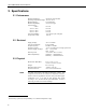
CS115 Barometric Pressure Sensor 2. Specifications 2.1 Performance Measurement Range: Operating Temperature Range: Humidity Range: Media Compatibility: 1 Total Accuracy : at 20°C -10°C to +50°C -20°C to +60°C -40°C to +60°C Long-term Stability: Overpressure Limit: 600 mb to 1100 mb (hPa) -40°C to +60°C non-condensing non-corrosive gas ±0.3 mb ±0.5 mb ±1.5 mb ±2.0 mb <0.11 mb per year (100 ppm) 1375 mb 2.
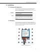
CS115 Barometric Pressure Sensor 3. Installation 3.1 Venting and Condensation To prevent condensation, install the sensor in an environmentally protected enclosure, complete with desiccant which should be changed at regular intervals. As the sensor must detect the external ambient pressure the enclosure must not be ‘hermetically sealed’. CAUTION Failure to protect the sensor from condensation may result in permanent damage.
CS115 Barometric Pressure Sensor As you mount the sensor onto the backplate of the enclosure, place the fork lug under the mounting screw to accomplish the proper grounding of the sensor as shown in Figure 3-1. 3.3 Jumper Settings The CS115 has two operating modes, ‘continuous’ and ‘triggered’. It is normally shipped in the ‘triggered’ mode, in which the unit is turned on and off by applying signal to the blue wire (EXT. TRIG.) using a datalogger’s control port.
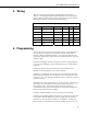
CS115 Barometric Pressure Sensor 4. Wiring The CS115 wiring instructions for the example programs are shown in Table 4-1. For dataloggers CR500, CR510, CR10(X), CR23X, and CR5000, analog channel is used for period averaging measurement. For CR7, 21X and CR9000 pulse channel is used for pulse count measurement. TABLE 4-1.
CS115 Barometric Pressure Sensor Once the CS115 is turned on one minute before every hour, and the correct measurement is made, it is then copied into the current variable called "Pressure". The sensor is then turned off immediately following the measurement. In this example, the CR5000 measures the CS115 once every hour while measuring other sensors at 10 Hz.
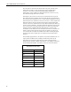
CS115 Barometric Pressure Sensor 5.1 Period Averaging Measurement Examples 5.1.1 Period Averaging Measurement Example for CR10(X) EXAMPLE 1.
CS115 Barometric Pressure Sensor 8: Sample (P70) 1: 1 2: 1* Reps Loc [ P_mb ] *Table 2 Program 02: 0.0000 Execution Interval (seconds) *Table 3 Subroutines End Program -Input Locations1 P_mb * Proper entries will vary with program and datalogger channel, and input location assignments. 5.1.2 Period Averaging Measurement Example for CR10(X) in a Slow Executing Program EXAMPLE 2.
CS115 Barometric Pressure Sensor ;Turn off CS115 ; 4: Do (P86) 1: 58* Set Port 8* Low 5: If time is (P92) 1: 0 Minutes (Seconds --) into a 2: 60 Interval (same units as above) 3: 10 Set Output Flag High (Flag 0) 6: Real Time (P77) 1: 0110 Day,Hour/Minute (midnight = 0000) 7: Sample (P70) 1: 1 2: 1* Reps Loc [ P_mb ] *Table 2 Program 02: 0.
CS115 Barometric Pressure Sensor 3: Period Average (SE) (P27) 1: 1 Reps 2: 14 200 kHz Max Freq @ 500 mV Peak to Peak, Freq Output 3: 24* SE Channel 4: 10 No. of Cycles 5: 5 Timeout (units = 0.01 seconds) 6: 1* Loc [ P_mb ] 7: 1000 Mult 8: 0.
CS115 Barometric Pressure Sensor 5.1.4 Period Averaging Measurement Example for CR5000 in a Fast Executing Program at 10Hz EXAMPLE 4. Sample Program for CR5000 ‘CR5000 ' 'Sample Program to Measure CS115 Barometric Pressure Sensor ' ' Public CS115_Freq, Pressure Units Pressure = mb BeginProg Scan (100,mSec,3,0) 'Turn CS115 ON one minute before every hour ' If (IfTime (59,60,min)) Then WriteIO (1,1) 'Period Avgeraging instruction must be executed every scan, and 'cannot be inside the "If" statement.
CS115 Barometric Pressure Sensor 5.2 Pulse Count Measurement Example 5.2.1 Pulse Count Measurement Example for 21X EXAMPLE 5. Sample Program for 21X ;{21X} ; *Table 1 Program 01: 1 Execution Interval (seconds) 1: If time is (P92) 1: 59 Minutes into a 2: 60 Minute Interval 3: 46* Set Port 6* High 2: If time is (P92) 1: 0 Minutes into a 2: 60 Minute Interval 3: 30 Then Do 3: Pulse (P3) 1: 1 2: 1* 3: 24 4: 1* 5: 1 6: 0.
CS115 Barometric Pressure Sensor *Table 3 Subroutines End Program -Input Locations1 P_mb 111 * Proper entries will vary with program and datalogger channel, and input location assignments. 5.3 Output Resolution When storing the values from the CS115 to a datalogger’s final storage location, or to a data table, care must be taken to choose suitable scaling of the reading or to store the value with adequate resolution to avoid losing useful resolution of the pressure measurement.
CS115 Barometric Pressure Sensor The corrections involved can be significant: e.g., at 1000 mb and 20°C, barometric pressure will decrease by 1.1 mb for every 10 meter increase in altitude. 7. Maintenance and Calibration Since the sensor is semi-sealed, minimum maintenance is required. 1. Visually inspect the cable connection to ensure it is clean and dry. 2. Ensure that the ground connection (shield) is secure and clean. 3. Visually inspect the casing for damage. 4.
This is a blank page.
Campbell Scientific Companies Campbell Scientific, Inc. (CSI) 815 West 1800 North Logan, Utah 84321 UNITED STATES www.campbellsci.com info@campbellsci.com Campbell Scientific Africa Pty. Ltd. (CSAf) PO Box 2450 Somerset West 7129 SOUTH AFRICA www.csafrica.co.za sales@csafrica.co.za Campbell Scientific Australia Pty. Ltd. (CSA) PO Box 444 Thuringowa Central QLD 4812 AUSTRALIA www.campbellsci.com.au info@campbellsci.com.au Campbell Scientific do Brazil Ltda.