
Product Manual

3
TF2101, TF2111, TQ3010, TQ3011, TX2101, TX2118
Installation (Continued)
Do not locate the
compressor air
inlet near steam, paint spray,
sandblast areas or any other source
of contamination.
NOTE: If compressor operates in a hot,
moist environment, supply compressor
pump with clean, dry outside air. Supply
air should be piped in from external
sources. For two-stage compressors
only, use adapter kit (TF060502AV)
to connect piping to compressor. Two
adapter kits are needed for two-stage
10 and 15 HP units.
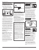
TANK MOUNTING
The tank should be bolted into a flat,
even, concrete floor or on a separate
concrete foundation. Vibration isolators
should be used between the tank leg
and the floor. Model MP367700AJ
isolator pads are recommended for
horizontal units. Model MP345700AJ
isolator pads are recommended for
vertical units. When using isolator
pads, do not draw bolts tight. Allow
the pads to absorb vibrations. When
isolators are used, a flexible hose or
coupling should be installed between
the tank and service piping.
Failure
to properly install the
tank can lead to cracks
at the welded joints and
possible bursting.
PIPING
Never use plastic
(PVC) pipe for
compressed air. Serious injury or
death could result.
Any tube, pipe or hose connected to
the unit must be able to withstand the
temperature generated and retain the
pressure. All pressurized components
of the air system must have a pressure
rating higher than or equal to the
200 psi for two-stage compressors or
150 psi for single stage compressors
ASME safety valve setting.
Incorrect selection and installation of
any tube, pipe or hose could result in
bursting and injury. Connect piping
system to tank using the same size
fitting as the discharge port.
INSTALLING A SHUT-OFF VALVE
A shut-off valve should be installed
on the discharge port of the tank to
control the air flow out of the tank.
The valve should be located between
the tank and the piping system.
Never install a
shut-off valve
between the compressor pump
and the tank. Personal injury and/
or equipment damage may occur.
Never use reducers in discharge
piping.
When creating a permanently installed
system to distribute compressed air,
find the total length of the system and
select pipe size from the chart. Bury
underground lines below the frost line
and avoid pockets where condensation
can gather and freeze.
Apply air pressure to the piping
installation and make sure all joints are
free from leaks BEFORE underground
lines are covered. Before putting the
compressor into service, find and repair
all leaks in the piping, fittings and
connections.
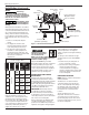
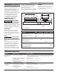
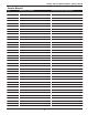
Chart 1: Minimum Pipe Size for
Compressed Air Line (in inches)
Length Of Piping
System (in feet)
CFM 25 50 100 250
10 1/2 1/2 3/4 3/4
20 3/4 3/4 3/4 1
40 3/4 1 1 1
60 3/4 1 1 1
100 1 1 1 1-1/4
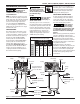
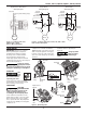
Drain Valve
Isolation Pad
(available separately)
Tank
Discharge
Port
Tank Shut-Off Valve
(available separately)
Discharge
Port
Tank Shut-Off Valve
(available separately)
Pressure
Gauge
Pressure
Gauge
Factory Mounted
Magnetic Starter
(not on all units)
Pressure
Switch
Pressure
Switch
Safety
Valve
Motor
Motor
Pump
Pump
Check
Valve
Discharge
Tube
Discharge
Tube
Safety Valve
Access
Figure 1 - Vertical Unit Identification