
Product Manual

Installation (Continued)
WIRING
All wiring
and electrical
connections must be performed by
a qualified electrician. Installations
must be in accordance with local
and national codes.
Overheating, short
circuiting and fire
damage will result from inadequate
wiring.
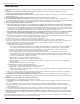
Wiring must be installed in accordance
with National Electrical Code and local
codes and standards that have been set
up covering electrical apparatus and
wiring. These should be consulted and
local ordinances observed. Be certain
that adequate wire sizes are used, and
that:
1. Service is of adequate ampere
rating.
2. The supply line has the same
electrical characteristics (voltage,
cycles and phase) as the motor.
3. The line wire is the proper size
and that no other equipment is
operated from the same line. The
chart gives minimum recommended
wire sizes for compressor
installations.
Recommended wire sizes may be larger
than the minimum set up by local
ordinances. If so, the larger size wire
should be used to prevent excessive
line voltage drop. The additional wire
cost is very small compared with the
cost of repairing or replacing a motor
electrically “starved” by the use of
supply wires which are too small.
GROUNDING
Improperly grounded
electrical components
are shock hazards.
Make sure all the components
are properly grounded to prevent
death or serious injury.
This product must be grounded.
Grounding reduces the risk of electrical
shock by providing an escape wire
for the electric current if short circuit
occurs. This product must be installed
and operated with a power cord or
cable that has a grounding wire.
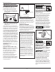
MOTOR HOOKUP AND STARTER
INSTALLATION
Branch circuit protection must be
provided as specified in the United
States National Electrical Code, Chapter
2, “Wiring Design and Protection.”
Article 210, using the applicable article
“For Motors and Motor Controllers,”
(Article 430, Table 430-1 52).
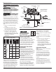
IMPORTANT: Overload protection
is required for all motors. Certain
motors have this protection built-in.
To determine if a motor has built-in
overload protection, refer to the frame
size on the motor nameplate.
Motors with frame size R56HZ, Y56Y
or L143T include built-in overload
protection. No additional protection is
required. Use Figure 3 wiring diagram.
Motors with frame sizes 184T, 215T,
254T or 284T do not have built-in
overload protection. A magnetic
starter is required. Use Figure 4 wiring
diagram.
To change to the alternate voltage
on three phase motors with 230/460
ratings:
1. Rewire motor per data plate on
motor or instruction sheet.
2. Check electric rating of magnetic
starter and replace thermal
overload elements or magnetic
starter as required. The voltage and
amperage ratings are listed on the
motor nameplate.
DIRECTION OF ROTATION
NOTE: Improper rotation will result in
reduced unit life.
The direction of rotation must be
counterclockwise (as shown by the
arrow on the flywheel) while facing
the flywheel side of the pump. The
motor nameplate will show wiring
information for counterclockwise
rotation.
The proper direction is very
important. The direction of rotation
of 3 phase motors can be reversed
by interchanging any two motor-line
leads. For single phase motors, refer to
the motor nameplate.
Operating Instructions
4
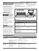
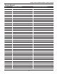
Chart 2: Minimum Wire Size
Use 75°C Copper Wire
Single
Phase
Three
Phase
HP
Amps
230 V
208 /
230 V
460 /
575 V
SPL
Up to 22.0
10
AWG
5.0
8
AWG
12
AWG
14
AWG
7.5
8
AWG
10
AWG
12
AWG
10.0
8
AWG
12
AWG
15.0
6
AWG
10
AWG
25.0
3
AWG
8
AWG
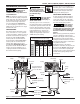
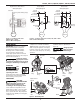
Isolation Pad
(available separately)
Tank
Tank Shut-Off Valve
(available separately)
Factory Mounted
Magnetic Starter
(not on all units)
Pump
Discharge
Tube
Motor
Safety Valve
Access
Figure 2 - Horizontal Unit Identification
Drain Valve
Discharge Port
Pressure Switch
Pressure
Gauge
Check
Valve