Model 020C Wind Direction Sensor Revision: 5/12 C o p y r i g h t © 2 0 1 2 C a m p b e l l S c i e n t i f i c , I n c .
Warranty “PRODUCTS MANUFACTURED BY CAMPBELL SCIENTIFIC, INC. are warranted by Campbell Scientific, Inc. (“Campbell”) to be free from defects in materials and workmanship under normal use and service for twelve (12) months from date of shipment unless otherwise specified in the corresponding Campbell pricelist or product manual. Products not manufactured, but that are re-sold by Campbell, are warranted only to the limits extended by the original manufacturer.
Assistance Products may not be returned without prior authorization. The following contact information is for US and international customers residing in countries served by Campbell Scientific, Inc. directly. Affiliate companies handle repairs for customers within their territories. Please visit www.campbellsci.com to determine which Campbell Scientific company serves your country. To obtain a Returned Materials Authorization (RMA), contact CAMPBELL SCIENTIFIC, INC., phone (435) 227-9000.
020C Table of Contents PDF viewers: These page numbers refer to the printed version of this document. Use the PDF reader bookmarks tab for links to specific sections. 1. Introduction..................................................................1 2. Cautionary Statements................................................1 3. Initial Inspection ..........................................................1 4. Quickstart .....................................................................1 4.1 Installation ...
020C Table of Contents Figures 4-1. Installation of 020C Wind Vane ............................................................. 2 7-1. 020C mounted with CM200-series crossarm and CM220 right-angle mounting bracket................................................................................. 9 7-2. 020C mounted with CM200-series crossarm and 1049 Nurail® fitting .. 9 A-1. Magnetic declination for the contiguous United States (2004).......... A-2 A-2.
Model 020C Wind Direction Sensor 1. Introduction The Model 020C Wind Direction Sensor measures azimuth with researchgrade accuracy and precision. Campbell Scientific recommends the 020C for wind farm power performance research, such as on eighty- and ninety-meter met towers. The 020C is especially suited to applications requiring a low starting threshold, a high damping ratio, or a short delay distance.
Model 020C Wind Direction Sensor 1. Remove the orientation screw from the base of the sensor column. Place the sensor column in the bushing such that the hole in the bushing aligns with the hole just vacated by the orientation screw. Replace the screw and tighten until snug. Do not over-tighten. 2. Place the sensor and bushing in the right-angle mounting bracket or Nurail® fitting. 3.
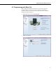
Model 020C Wind Direction Sensor 4.2 Programming with Short Cut Short Cut Program Generator for Windows can be used to program the CR1000 datalogger to measure the 020C as outlined in the following procedure. Short Cut can also be used to program other 020C-compatible Campbell Scientific dataloggers. 1. Open Short Cut and click on New Program. 2. Select a scan interval.
Model 020C Wind Direction Sensor 4 3. Select 020C Wind Direction Sensor and select the right arrow to add it to the list of sensors to be measured. 4. Define the name of the public variable (WindDir) that holds the wind direction measurement. When the sensor points south with the hub and column notches aligned, no installation-offset correction is required.
Model 020C Wind Direction Sensor 5. Sensor connections to the CR1000 datalogger are shown in the Wiring tab. In applications with tight power budgets, the power connection can be connected to a controlled 12-Vdc terminal or device. See Section 7, Installation. 6. Select the desired output data for final storage and click Finish.
Model 020C Wind Direction Sensor 7. A full description of sensor wiring can be found by selecting Wiring Diagram at the left of the Short Cut window. Send the program from the PC to the CR1000 datalogger if the telecommunications link is active. 5. Overview 5.1 Operation The lightweight, airfoil vane is directly coupled to a single precision microtorque potentiometer.
Model 020C Wind Direction Sensor 6.
Model 020C Wind Direction Sensor 7. Installation Before installation: • Check to see that the vane assembly rotates freely. • Ensure that the vane assembly is balanced and the counterweight is tight by holding the sensor horizontal to verify balance. 7.1 Select Output Range The output voltage range of the 020C is pre-set at 0 to 5 Vdc at a jumper under the outer cover of the main body of the probe. The cover is held in place by friction fit against two O-rings. To change the range to 0 to 2.
Model 020C Wind Direction Sensor Alignment set screw CM220 mounting bracket Bushing CM200-series crossarm FIGURE 7-1. 020C mounted with CM200-series crossarm and CM220 right-angle mounting bracket Alignment screw CM200-series crossarm Bushing 1 x 3/4 Nurail® fitting FIGURE 7-2. 020C mounted with CM200-series crossarm and 1049 Nurail® fitting 7.4 Wiring Attach the sensor cable to the six-pin male connector on the 020C. Make sure the connector is properly keyed. Finger-tighten the knurled ring.
Model 020C Wind Direction Sensor TABLE 7-1. 020C Wiring Wire Color Wire Description CR23X CR800-series CR1000 CR3000 CR5000 CR10(X) CR500 CR510 White Power 12V 12V 12V Green Ground G G Blue Signal SE input SE input Red (Optional) Heater + Supply 12V Supply 12V Black* (Optional) Heater - Supply ground Supply ground Clear Shield * G *Bearing heat only.
Model 020C Wind Direction Sensor 'Main Program BeginProg 'Main Scan Scan(1,Sec,1,0) 'Default Datalogger Battery Voltage measurement 'BattV' Battery(BattV) 'Default Wiring Panel Temperature measurement 'PTemp_C' PanelTemp(PTemp_C,_60Hz) '020C Wind Direction Sensor measurement 'WindDir' VoltSe(WindDir,1,mV5000,1,1,0,_60Hz,0.
Model 020C Wind Direction Sensor 8. Troubleshooting and Maintenance 8.1 Troubleshooting Consult Table 8-1 for recommended actions to resolve various fault conditions. TABLE 8-1. 020C Wind Direction Sensor Troubleshooting Symptom Probable Cause Solution Refer to No wind direction output Loss of supply voltage Check datalogger 12Vdc supply and connecting cables Table 7-1, 020C Wiring No wind direction output Faulty integrated circuit amplifier (output often will be steady 5.
Model 020C Wind Direction Sensor EPA, 1987: On-Site Meteorological Program Guidance for Regulatory Modeling Applications, EPA-450/4-87-013, Office of Air Quality Planning and Standards, Research Triangle Park, NC 27711. The State Climatologist, 1985: Publication of the American Association of State Climatologists: Height and Exposure Standards, for Sensors on Automated Weather Stations, vol. 9, No. 4.
Model 020C Wind Direction Sensor 14
Appendix A. Wind Direction Sensor Orientation A.1 Determining True North and Sensor Orientation Orientation of the wind direction sensor is done after the datalogger has been programmed, and the location of true North has been determined. True North is usually found by reading a magnetic compass and applying the correction for magnetic declination; where magnetic declination is the number of degrees between true North and Magnetic North.
Appendix A. Wind Direction Sensor Orientation FIGURE A-1.
Appendix A. Wind Direction Sensor Orientation FIGURE A-2. Declination angles east of true North are subtracted from 360° to get true North FIGURE A-3.
Appendix A.
Campbell Scientific Companies Campbell Scientific, Inc. (CSI) 815 West 1800 North Logan, Utah 84321 UNITED STATES www.campbellsci.com • info@campbellsci.com Campbell Scientific Africa Pty. Ltd. (CSAf) PO Box 2450 Somerset West 7129 SOUTH AFRICA www.csafrica.co.za • cleroux@csafrica.co.za Campbell Scientific Australia Pty. Ltd. (CSA) PO Box 8108 Garbutt Post Shop QLD 4814 AUSTRALIA www.campbellsci.com.au • info@campbellsci.com.au Campbell Scientific do Brazil Ltda.