4WFB120, 4WFB350, 4WFB1K 4 Wire Full Bridge Terminal Input Modules Revision: 5/07 C o p y r i g h t © 1 9 9 6 - 2 0 0 7 C a m p b e l l S c i e n t i f i c , I n c .
Warranty and Assistance The 4WFB120, 4WFB350, 4WFB1K 4 WIRE FULL BRIDGE TERMINAL INPUT MODULES are warranted by CAMPBELL SCIENTIFIC, INC. to be free from defects in materials and workmanship under normal use and service for twelve (12) months from date of shipment unless specified otherwise. Batteries have no warranty. CAMPBELL SCIENTIFIC, INC.'s obligation under this warranty is limited to repairing or replacing (at CAMPBELL SCIENTIFIC, INC.'s option) defective products.
4WFB120, 4WFB350, 4WFB1K Table of Contents PDF viewers note: These page numbers refer to the printed version of this document. Use the Adobe Acrobat® bookmarks tab for links to specific sections. 1. Function........................................................................1 2. Specifications ..............................................................1 3. Measurement Concepts ..............................................2 4. Wiring...................................................................
This is a blank page.
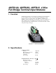
4WFB120, 4WFB350, 4WFB1K 4 Wire Full Bridge Terminal Input Modules 1. Function Terminal input modules connect directly to the datalogger's input terminals to provide completion resistors for resistive bridge measurements, voltage dividers, and precision current shunts. The 4WFB120, 4WFB350, and 4WFB1K complete a full bridge for a strain gage or other sensor that acts as a single variable resistor.
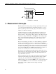
4WFB120, 4WFB350, 4WFB1K 4 Wire Full Bridge Terminal Input Modules Vx H H H 120 Ω , 350 Ω , or 1kΩ 1kΩ L or AG L 1kΩ G FIGURE 2-1. Schematic 3. Measurement Concepts Measuring strain is measuring a change in length. Specifically, the unit strain (ε ) is the change in length divided by the unstrained length (ε = ∆ l / l ) . Strain is typically reported in microstrain ( µε ) ; a microstrain is a change in length by one millionth of the length.
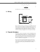
4WFB120, 4WFB350, 4WFB1K 4 Wire Full Bridge Terminal Input Modules Vr = (Vout / Vex ) − (Vout 0 / Vex ) : ε = 4V r G F (1 − 2V r ) 3.1. 3.2. The calculations are covered in more detail in section 6. 4. Wiring Datalogger Vx H H H L L or AG G or G Shield FIGURE 4-1. Wiring for Example Programs Figure 4-1 illustrates the wiring of the strain gage to the 4WFB module and the wiring of the module to the datalogger.
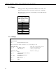
4WFB120, 4WFB350, 4WFB1K 4 Wire Full Bridge Terminal Input Modules 5.1 Edlog Dataloggers that use Edlog include CR510, CR10(X), 21X, and CR7. The Edlog instruction that measures strain gages is Instruction 6 – Full Bridge. The Input Locations assignments used in CR10(X), 21X, and CR7 Examples are listed in Table 5-1. TABLE 5-1. Input Locations Used in CR10(X), 21X, and CR7 Examples Addr 1 2 3 4 5 6 7 8 9 10 Name mVperV mVperV_0 Vr uStrain Count GF _4e6 Mult 1_2Vr Vr_1_2Vr 5.1.
4WFB120, 4WFB350, 4WFB1K 4 Wire Full Bridge Terminal Input Modules 3: X-Y (P35) 1: 1 2: 2 3: 3 4: X*F (P37) 1: 3 2: 0.
4WFB120, 4WFB350, 4WFB1K 4 Wire Full Bridge Terminal Input Modules *Table 3 Subroutines 1: Beginning of Subroutine (P85) 1: 1 Subroutine 1 ;Subroutine to measure "zero" 2: Do (P86) 1: 11 Set Flag 1 High ;This prevents calling subroutine ;until user sets flag 1 low again.
4WFB120, 4WFB350, 4WFB1K 4 Wire Full Bridge Terminal Input Modules 11: Set Active Storage Area (P80) ;Direct averaged "zero" reading 1: 3 Input Storage Area ;to input storage 2: 2 Array ID or Loc [ mVperV_0 ] 12: Average (P71) 1: 1 Reps 2: 1 Loc [ mVperV ] 13: If Flag/Port (P91) ;When average is calculated, 1: 10 Do if Output Flag is High (Flag 0) ;also send it to Final Storage 2: 10 Set Output Flag High 14: Set Active Storage Area (P80) 1: 1 Final Storage Area 1 2: 11 Array ID ;Direct Output to Final S
4WFB120, 4WFB350, 4WFB1K 4 Wire Full Bridge Terminal Input Modules 3: Z=X-Y (P35) 1: 1 2: 2 3: 3 X Loc [ mVperV ] Y Loc [ mVperV_0 ] Z Loc [ Vr ] 4: Z=X*F (P37) 1: 3 2: 0.
4WFB120, 4WFB350, 4WFB1K 4 Wire Full Bridge Terminal Input Modules *Table 3 Subroutines 1: Beginning of Subroutine (P85) 1: 1 Subroutine 1 ;Subroutine to measure "zero" 2: Do (P86) 1: 11 Set Flag 1 High ;This prevents calling subroutine ;until user sets flag 1 low again.
4WFB120, 4WFB350, 4WFB1K 4 Wire Full Bridge Terminal Input Modules 12: Set Active Storage Area (P80) ;Direct averaged "zero" reading 1: 3 Input Storage ;to input storage 2: 2 Array ID or Loc [ mVperV_0 ] 13: Average (P71) 1: 1 Reps 2: 1 Loc [ mVperV ] 14: If Flag/Port (P91) ;When average is calculated, 1: 10 Do if Output Flag is High (Flag 0) ;also send it to Final Storage 2: 10 Set Output Flag High 15: Set Active Storage Area (P80) 1: 1 Final Storage 2: 11 Array ID ;Direct Output to Final Storage ;set
4WFB120, 4WFB350, 4WFB1K 4 Wire Full Bridge Terminal Input Modules 3: Z=X-Y (P35) 1: 1 2: 2 3: 3 X Loc [ mVperV ] Y Loc [ mVperV_0 ] Z LOC [ Vr ] 4: Z=X*F (P37) 1: 3 2: 0.
4WFB120, 4WFB350, 4WFB1K 4 Wire Full Bridge Terminal Input Modules *Table 2 Program 01: 0.0000 Execution Interval (seconds) *Table 3 Subroutines 1: Beginning of Subroutine (P85) 1: 1 Subroutine 1 ;Subroutine to measure "zero" 2: Do (P86) 1: 11 Set Flag 1 High ;This prevents calling subroutine ;until user sets flag 1 low again.
4WFB120, 4WFB350, 4WFB1K 4 Wire Full Bridge Terminal Input Modules 11: IF (X<=>F) (P89) 1: 5 X Loc [ Count ] 2: 3 >= 3: 5 F 4: 10 Set Output Flag High ;Check for last pass through loop ;to set output flag 12: Set Active Storage Area (P80) ;Direct averaged "zero" reading 1: 3 Input Storage ;to input storage 2: 2 Array ID or Loc [ mVperV_0 ] 13: Average (P71) 1: 1 Reps 2: 1 Loc [ mVperV ] 14: If Flag/Port (P91) ;When average is calculated, 1: 10 Do if Output Flag is High (Flag 0) ;also send it to Final S
4WFB120, 4WFB350, 4WFB1K 4 Wire Full Bridge Terminal Input Modules 5.2.1 CR9000(X) This example program is slightly different in operation than the examples for the other dataloggers. Data are only output to data table STRAINS when the user sets Flag(1). Every measurement is output (rather than averages like in the other examples) while Flag(1) is high. ' Program name: STRAIN.
4WFB120, 4WFB350, 4WFB1K 4 Wire Full Bridge Terminal Input Modules 6. Calculation of Strain Vx H H H R1 R3 L L Rg R2 or AG G FIGURE 6-1. Strain Gage in Full Bridge Figure 6-1 is the diagram of the strain gage in the full bridge configuration provided by the terminal input module.
4WFB120, 4WFB350, 4WFB1K 4 Wire Full Bridge Terminal Input Modules Subtracting the unstrained (zero) result from the strained result gives Vr : Rg + ∆Rg Rg ⎛Vout ⎞ ⎛Vout ⎞ ⎟ ⎟ − Vr = ⎜ −⎜ = ⎝ Vin ⎠ strained ⎝ Vin ⎠ unstrained R3 + Rg + ∆Rg R3 + Rg = R3 ⋅ ∆Rg 6.6. ( R3 + Rg + ∆Rg ) ⋅ ( R3 + Rg ) The terminal input module is selected so that R3 = Rg . Substituting Rg for R3 : Vr = R g ⋅ ∆R g ( Rg + Rg + ∆ Rg ) ⋅ ( Rg + Rg ) = Rg ⋅ ∆ Rg 4 R g + 2 Rg ∆ R g 2 = ∆ Rg 6.7.
This is a blank page.
Campbell Scientific Companies Campbell Scientific, Inc. (CSI) 815 West 1800 North Logan, Utah 84321 UNITED STATES www.campbellsci.com info@campbellsci.com Campbell Scientific Africa Pty. Ltd. (CSAf) PO Box 2450 Somerset West 7129 SOUTH AFRICA www.csafrica.co.za cleroux@csafrica.co.za Campbell Scientific Australia Pty. Ltd. (CSA) PO Box 444 Thuringowa Central QLD 4812 AUSTRALIA www.campbellsci.com.au info@campbellsci.com.au Campbell Scientific do Brazil Ltda.