
User Manual
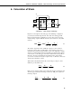

4WFB120, 4WFB350, 4WFB1K 4 Wire Full Bridge Terminal Input Modules
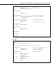
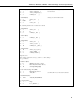
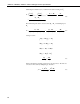
*Table 2 Program
01: 0.0000 Execution Interval (seconds)
*Table 3 Subroutines
1: Beginning of Subroutine (P85) ;Subroutine to measure "zero"
1: 1 Subroutine 1
2: Do (P86) ;This prevents calling subroutine
1: 11 Set Flag 1 High ;until user sets flag 1 low again.
3: Z=F (P30) ;Set counter use for average to 0
1: 0 F
2: 5 Z LOC [ Count ]
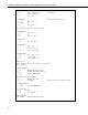
4: Z=F (P30) ;load 4000 into
1: 4000 F ;input location
2: 7 Z LOC [ 4e6 ]
5: Z=X*F (P37) ;Multiply by 1000 to get (4*uS/S)
1: 7 X Loc [ 4e6 ]
2: 1000 F
3: 7 Z LOC [ 4e6 ]
6: Z=F (P30) ;Load Gage Factor into input location
1: 2 F ;Enter the actual Gage Factor here
2: 6 Z LOC [ GF ]
7: Z=X/Y (P38) ;calculate multiplier to use with strain
1: 7 X Loc [ 4e6 ] ;calculation
2: 6 Y Loc [ GF ]
3: 8 Z LOC [ Mult ]
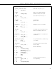
8: Beginning of Loop (P87) ;Loop through 5 times to obtain average
1: 0 Delay ;zero reading
2: 5 Loop Count
9: Z=Z+1 (P32) ;Increment Counter used to determine
1: 5 Z Loc [ Count ] ;when to output
10: Full Bridge (P6) ;Measure Strain Gage
1: 1 Reps
2: 3 ± 15 mV Slow Range
3: 1 In Card
4: 1 DIFF Channel
5: 1 Ex Card
6: 1 Ex Channel
7: 1 Meas/Ex
8: 5000 mV Excitation
9: 1 Loc [ mVperV ]
10: 1 Mult
11: 0 Offset
12