4WFBS120, 4WFBS350, 4WFBS1K 4 Wire Full Bridge Terminal Input Modules Revision: 3/12 C o p y r i g h t © 1 9 9 6 - 2 0 1 0 C a m p b e l l S c i e n t i f i c , I n c .
Warranty “PRODUCTS MANUFACTURED BY CAMPBELL SCIENTIFIC, INC. are warranted by Campbell Scientific, Inc. (“Campbell”) to be free from defects in materials and workmanship under normal use and service for twelve (12) months from date of shipment unless otherwise specified in the corresponding Campbell pricelist or product manual. Products not manufactured, but that are re-sold by Campbell, are warranted only to the limits extended by the original manufacturer.
Assistance Products may not be returned without prior authorization. The following contact information is for US and international customers residing in countries served by Campbell Scientific, Inc. directly. Affiliate companies handle repairs for customers within their territories. Please visit www.campbellsci.com to determine which Campbell Scientific company serves your country. To obtain a Returned Materials Authorization (RMA), contact CAMPBELL SCIENTIFIC, INC., phone (435) 227-9000.
4WFBS120, 4WFBS350, 4WFBS1K Table of Contents PDF viewers: These page numbers refer to the printed version of this document. Use the PDF reader bookmarks tab for links to specific sections. 1. Function........................................................................1 2. Specifications ..............................................................1 3. Measurement Concepts ..............................................2 4. Quarter Bridge Strain ..................................................4 4.
4WFBS120, 4WFBS350, 4WFBS1K Table of Contents Figures 1-1. Terminal Input Module with CR1000 .................................................... 1 2-1. Schematic................................................................................................ 2 3-1. Strain definition ...................................................................................... 2 4.1-1. Three wire quarter bridge strain circuit ............................................... 4 4.1-2. 3-wire ¼ bridge strain wiring ...
4WFBS120, 4WFBS350, 4WFBS1K 4 Wire Full Bridge Terminal Input Modules (TIM) 1. Function The 4WFBS120, 4WFBS350, and 4WFBS1K Terminal Input Modules (TIM) complete a full Wheatstone bridge for a single strain gage or other sensor that acts as a single variable resistor. The difference between the three models is in the resistor that matches the nominal resistance of a 120 ohm, 350 ohm, or 1000 ohm quarter bridge strain gage.
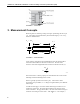
4WFBS120, 4WFBS350, 4WFBS1K 4 Wire Full Bridge Terminal Input Modules (TIM) FIGURE 2-1. Schematic 3. Measurement Concepts Measuring strain is measuring a change in length. Specifically, the unit strain (ε ) is the change in length divided by the unstrained length ε = Δ L / L , and thus is dimensionless. ( LT + ΔLT ) LT L P P L + ΔL FIGURE 3-1. Strain definition As the subject is elongated in the longitudinal direction, the material will be narrowed or thinned down in the transverse direction.
4WFBS120, 4WFBS350, 4WFBS1K 4 Wire Full Bridge Terminal Input Modules (TIM) gage factor of 2 means that if the length changes by one micrometer per meter of length (1 με ) , the resistance will change by two micro-ohms per ohm of resistance. A more common method of portraying this equation is: ε= ΔRG GF • RG 3.2 Or in terms of micro-strain: με = (1×10 )ΔR 6 G GF • RG 3.3 Because the actual change in resistance is small, a full Wheatstone bridge configuration is used to give the maximum resolution.
4WFBS120, 4WFBS350, 4WFBS1K 4 Wire Full Bridge Terminal Input Modules (TIM) function used in CRBasic uses this raw output as its input to calculate µstrain. See Section 4.5 Calculation of Strain for ¼ Bridge Circuits for a detailed derivation of the equations used. 4. Quarter Bridge Strain A "quarter bridge strain circuit" is so named because an active strain gage is used as one of the four resistive elements that make up a full Wheatstone bridge.
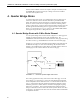
4WFBS120, 4WFBS350, 4WFBS1K 4 Wire Full Bridge Terminal Input Modules (TIM) 4.1.1 Quarter Bridge Strain with 3 Wire Element Wiring Figure 4.1-2 illustrates the wiring of the strain gage to the 4WFBS module and the wiring of the module to the datalogger. It is important that the gage be wired as shown, and that the leads to the L and G terminals be the same length, diameter, and wire type.
4WFBS120, 4WFBS350, 4WFBS1K 4 Wire Full Bridge Terminal Input Modules (TIM) Although this requires a 4WFBS module for each strain gage, it is important because placing relays internal a Wheatstone bridge strain system is discouraged. Any change in resistance of the multiplexer’s relay contacts would result in a corresponding change in the bridge’s output voltage.
4WFBS120, 4WFBS350, 4WFBS1K 4 Wire Full Bridge Terminal Input Modules (TIM) 4.1.3 Quarter Bridge Strain with 3 Wire Program Examples This section is broken out into CRBasic programs and EDLOG programs. These programs are only to be used as examples. Besides adding additional measurement instructions, the programs will need to have the scan and data storage intervals altered for actual applications.
4WFBS120, 4WFBS350, 4WFBS1K 4 Wire Full Bridge Terminal Input Modules (TIM) Scan(10,mSec,100,0) 'Scan once every 10 mSecs, non-burst BrFull(StrainMvperV(),3,mV50,4,1,5,7,1,5000,True,True,70,100,1,0) StrainCalc(Strain(),3,StrainMvperV(),0,-1,GF(),0) 'Strain calculation CallTable STRAIN Next Scan 'Loop up for the next scan SlowSequence Scan(1,Sec,0,0) Calibrate BiasComp Next Scan EndProg 'Slow sequence Scan to perform temperature ' compensation on DAQ 'Corrects ADC offset and gain 'Corrects ADC bias current
4WFBS120, 4WFBS350, 4WFBS1K 4 Wire Full Bridge Terminal Input Modules (TIM) BeginProg 'Program begins here GF(1) = 2.1 : GF(2) = 2.2 : GF(3) = 2.
4WFBS120, 4WFBS350, 4WFBS1K 4 Wire Full Bridge Terminal Input Modules (TIM) Example Program 4.3. CR1000 ¼ Bridge Strain using an AM16/32B Multiplexer with 16 reps and zero offset This example program has 16 strain gages multiplexed through an AM16/32 Multiplexer and uses FieldCalStrain for zeroing. ' Program name: QuarterStrain with Zero and Mux.
4WFBS120, 4WFBS350, 4WFBS1K 4 Wire Full Bridge Terminal Input Modules (TIM) Scan(1,Sec,10,0) 'Scan once a Second PortSet (1 ,1 ) 'Turn on AM16/32 using C1 I=1 Delay (0,150,mSec) 'required Delay for AM16/32 multiplexer SubScan (0,0,16) PulsePort (2,10000) 'Pulse port C2 hi and low to clock the multiplexer BrFull(MVpV(I),1,mV7_5C,1,VX1,1,2500,True,True,250,500,1,0) 'Full Bridge measurement StrainCalc(Strain(I),1,MVpV(I),mV_VZero(I),-1,GF(I),0) 'Strain calculation I=I+1 'Increment I NextSubScan PortSet (1 ,0
4WFBS120, 4WFBS350, 4WFBS1K 4 Wire Full Bridge Terminal Input Modules (TIM) Example Program 4.4. CR10X ¼ Bridge Strain with 1 rep and zero offset ;{CR10X} *Table 1 Program 01: 1 Execution Interval (seconds) 1: If Flag/Port (P91) 1: 21 Do if Flag 1 is Low 2: 1 Call Subroutine 1 ;On the first execution (Flag 1 is low) ;or when user sets Flag 1 low ;call the zeroing subroutine 2: Full Bridge (P6) 1: 1 2: 22 3: 1 4: 1 5: 2500 6: 1 7: 1 8: 0 ;Measure the strain gage Reps ± 7.
4WFBS120, 4WFBS350, 4WFBS1K 4 Wire Full Bridge Terminal Input Modules (TIM) 12: Average (P71) 1: 1 2: 4 Reps Loc [ uStrain ] *Table 2 Program 2: 0.0000 Execution Interval (seconds) *Table 3 Subroutines 1: Beginning of Subroutine (P85) 1: 1 Subroutine 1 ;Subroutine to measure "zero" 2: Do (P86) 1: 11 Set Flag 1 High ;This prevents calling subroutine ;until user sets flag 1 low again.
4WFBS120, 4WFBS350, 4WFBS1K 4 Wire Full Bridge Terminal Input Modules (TIM) 12: Average (P71) 1: 1 2: 1 Reps Loc [ mVperV ] 13: If Flag/Port (P91) 1: 10 Do if Output Flag is High (Flag 0) 2: 10 Set Output Flag High ;When average is calculated, ;also send it to Final Storage 14: Set Active Storage Area (P80) 1: 1 Final Storage Area 1 2: 11 Array ID ;Direct Output to Final Storage ;set Array ID = 11 for zero data 15: Real Time (P77) 1: 110 Day,Hour/Minute 16: Sample (P70) 1: 1 2: 2 Reps Loc [ mVperV_0
4WFBS120, 4WFBS350, 4WFBS1K 4 Wire Full Bridge Terminal Input Modules (TIM) ;The following instructions calculate microstrain 5: Z=X*F (P37) 1: 3 2: -2 3: 9 X Loc [ Vr ] F Z Loc [ 1_2Vr ] 6: Z=Z+1 (P32) 1: 9 Z Loc [ 1_2Vr 7: Z=X/Y (P38) 1: 3 2: 9 3: 10 X Loc [ Vr ] Y Loc [ 1_2Vr ] Z Loc [ Vr_1_2Vr ] 8: Z=X*Y (P36) 1: 10 2: 8 3: 4 X Loc [ Vr_1_2Vr ] Y Loc [ Mult ] Z Loc [ uStrain ] ] ;Output Section ;This example outputs an average of the 1 second readings ;once per minute.
4WFBS120, 4WFBS350, 4WFBS1K 4 Wire Full Bridge Terminal Input Modules (TIM) 6: Z=F (P30) 1: 2 2: 6 F Z Loc [ GF ;Load Gage Factor into input location ;Enter the actual Gage Factor here ] 7: Z=X/Y (P38) 1: 7 2: 6 3: 8 X Loc [ 4e6 Y Loc [ GF Z Loc [ Mult ] ] ] 8: Beginning of Loop (P87) 1: 0 Delay 2: 5 Loop Count ;Loop through 5 times to obtain average ;zero reading 9: Z=Z+1 (P32) 1: 5 Z Loc [ count 10: Full Bridge (P6) 1: 1 2: 2 3: 1 4: 1 5: 5000 6: 1 7: 1 8: 0 ;Measure Strain Gage Reps ± 15 mV S
4WFBS120, 4WFBS350, 4WFBS1K 4 Wire Full Bridge Terminal Input Modules (TIM) 4.2 Quarter Bridge Strain with 2 Wire Element NOTE Although a two wire gage can be used with the 4WFBS TIM, due to the issues outlined in Section 4.4.3, it is not recommended. An exception may be applications with short leads in a stable temperature environment. A 2-wire quarter bridge strain circuit is shown in figure 4.2-1. RD R2=1KΩ Excite V - + R4=Gauge R1=1KΩ FIGURE 4.2-1.
4WFBS120, 4WFBS350, 4WFBS1K 4 Wire Full Bridge Terminal Input Modules (TIM) Datalogger Vx H H H Jumper Wire L R2 R1 or AG or G RD L G Gauge Shield FIGURE 4.2-2. Wiring for 2-wire gauges 4.2.2 Two Wire ¼ Bridge use with Multiplexers and Equations The equations to resolve the strain, programming of the logger, and methods of using with multiplexers are the same as those covered in Section 4.1 for the 3Wire Strain gauge. The only variance is the wiring of the gage to the TIM. 4.
4WFBS120, 4WFBS350, 4WFBS1K 4 Wire Full Bridge Terminal Input Modules (TIM) Another temperature induced error in a quarter bridge strain circuit is due to the Temperature Coefficient of Resistance (TCR) of the completion resistor in the arm opposite the strain gauge. The 4WFBS TIMs use a high quality resistor having a TCR of 0.8ppm/°C to minimize these errors.
4WFBS120, 4WFBS350, 4WFBS1K 4 Wire Full Bridge Terminal Input Modules (TIM) The 4WFBS modules can support quarter bridge strain circuits using either the completion resistor built into the TIM, or a user supplied “dummy” strain gauge, for the Wheatstone Bridge arm's resistive element opposite of the active strain gauge in the bridge. Wiring circuits using a dummy gage are covered in Section 4.3.1. 4.3.1 Quarter Bridge Strain with Dummy Gauge Wiring Setup Figure 4.
4WFBS120, 4WFBS350, 4WFBS1K 4 Wire Full Bridge Terminal Input Modules (TIM) With either circuit, one lead leg, L1 or L3, is in one of the two opposing arms of the Wheatstone bridge. It is important that the gage be wired such, and that these two leads be the same length, diameter and wire type. It is preferable to use a twisted pair for these two wires so that they will undergo the same temperature and electromagnetic field variations.
4WFBS120, 4WFBS350, 4WFBS1K 4 Wire Full Bridge Terminal Input Modules (TIM) 4.4.1.1 Mathematical Lead Compensation Circuit and Equations If the lead resistance is known, the sensitivity error can be mathematically corrected for by multiplying the output by a simple factor (1+RL/RG) where RL is the nominal resistance of one of the lead legs and RG is the resistance of the strain gauge. The Gauge Factor can be multiplied by the inverse of this value, RG/(RG+ RL), to derive an adjusted Gauge Factor.
4WFBS120, 4WFBS350, 4WFBS1K 4 Wire Full Bridge Terminal Input Modules (TIM) Assume RD = RG VR = RG + RL + ΔRG R + RL − G 2RL + 2RG + ΔR G 2RG + 2RL 4.4.5 RG ΔRG + RL ΔRG + 2RL + ΔRG )(2RG + 2RL ) 4.4.6 Simplify VR = (2R G Solve for ΔRG/RG ΔRG 4VR ⎛ RG + RL ⎞ ⎜ ⎟ = (1 - 2VR ) ⎜⎝ RG ⎟⎠ RG 4.4.7 ⎛ ⎜ ⎝ Use the Gauge Factor to calculate micro-strain ⎜ με = με = 4V R × 10 6 ⎛ RG + R L ⎜ GF (1 - 2V R ) ⎜⎝ RG ΔR ×106 ⎞ ⎟ RG ×GF ⎟⎠ ⎞ ⎟⎟ ⎠ 4.4.8 4.4.1.
4WFBS120, 4WFBS350, 4WFBS1K 4 Wire Full Bridge Terminal Input Modules (TIM) BeginProg 'Program begins here GF(1) = 2.1 : GF(2) = 2.2 : GF(3) = 2.3 'Initialize gauge factors for Strain( ) LeadLength(1) = 1.25 ' load lead lengths (100s of feet) LeadLength(2) = 1.50 LeadLength(3) = 2.00 LeadRper100ft = 2.5 '24 gauge copper wire lead R is 0.
4WFBS120, 4WFBS350, 4WFBS1K 4 Wire Full Bridge Terminal Input Modules (TIM) Example Program 4.7. CR10X ¼ Bridge Strain with 16 reps, using multiplexer with zero offset and Lead Compensation Calculations using Lead resistance Addr 1 2 3 4 5 6 7 8 9 10 11 12 13 14 15 16 17 18 19 20 21 22 23 24 25 26 27 28 29 30 31 32 33 34 35 Name Input Locations Used in CR10(X)Program Example X.
4WFBS120, 4WFBS350, 4WFBS1K 4 Wire Full Bridge Terminal Input Modules (TIM) ;{CR10X} ;16SGMux.CSI ;This program calculates the strain for 16 quarter strain bridges using4 wire bridge completion modules. ; It takes into account the sensitivity changes due to lead length resistance. ;(1) Sensors: ; 16 strain gauges multiplexed through an AM416 ;(2) DataInfo: ; Strain gauges will be measured every 5 seconds. ; Only measurement at top of minute will be stored.
4WFBS120, 4WFBS350, 4WFBS1K 4 Wire Full Bridge Terminal Input Modules (TIM) 11: Z=X-Y (P35) ; 1: 1 -- X Loc [ mVPerVG01 ] 2: 17 -- Y Loc [ mVPerVZ01 ] 3: 33 Z Loc [ Vr_1 ] Subtract zeroed value from measurement.
4WFBS120, 4WFBS350, 4WFBS1K 4 Wire Full Bridge Terminal Input Modules (TIM) 5: Bulk Load (P65) 1: 5 F; 2: 9 F; 3: 12 F; 4: 4 F; 5: 8 F; 6: 2 F; 7: 8 F; 8: 9 F; 9: 78 Loc [ LeadFt09 ] 6: Beginning of Loop (P87) ; 1: 0 Delay 2: 16 Loop Count Gage09 Gage10 Gage11 Gage12 Gage13 Gage14 Gage15 Gage16 Calculate lead length resistance: 7: Z=X*Y (P36) 1: 70 -- X Loc [ LeadFt01 ] 2: 69 Y Loc [ LeadOhms ] 3: 86 -- Z Loc [ OhmLead01 ] 8: End (P95) 9: Bulk Load (P65) ; 1: 2.095 F ; 2: 2.095 F ; 3: 2.095 F ; 4: 2.
4WFBS120, 4WFBS350, 4WFBS1K 4 Wire Full Bridge Terminal Input Modules (TIM) 7: 350 8: 350 9: 126 F; F; Loc [ G09Ohms ] 13: Z=F (P30) ; 1: 4 F 2: 3 Exponent of 10 3: 68 Z Loc [ Number4e3 ] 14: Beginning of Loop (P87) ; 1: 0 Delay 2: 16 Loop Count Gage15 Gage16 Load in the large number, 4000.
4WFBS120, 4WFBS350, 4WFBS1K 4 Wire Full Bridge Terminal Input Modules (TIM) 31: Sample (P70)^16425 1: 16 Reps 2: 52 Loc [ uStrain01 ] 32: Do (P86) 1: 20 Set Output Flag Low (Flag 0) 33: End (P95) End Program 4.4.2 Shunt Calibration Lead Compensation for 3-Wire, ¼ Bridge Strain NOTE Although the following may seem complicated, the process of performing a Shunt calibration is simple when using the Calibration Wizard utility found in CSI’s software packages.
4WFBS120, 4WFBS350, 4WFBS1K 4 Wire Full Bridge Terminal Input Modules (TIM) RD R2= 1KΩ - RL + RL RS Gauge R1= 1KΩ RL FIGURE 4.4-2. Shunting remotely across active gauge RL represents the line resistances. RD is the resistor in the arm next to the active gage which has a resistance equal to the nominal resistance of the Strain gauge and is referred to as the Dummy Resistor. Rs is the Shunt resistor. This setup is the classical method for shunting a 3-wire ¼ bridge strain circuit. 4.4.2.1.
4WFBS120, 4WFBS350, 4WFBS1K 4 Wire Full Bridge Terminal Input Modules (TIM) NOTE It should be noted that a shunt resistor should not be connected across the active gauge’s leads back at the completion portion of the Wheatstone Bridge, as this would not correctly account for the leads resistances. If performing a shunt back at the instrumentation location, it must be done across the Dummy Resistor as shown in figure 4.4-3.
4WFBS120, 4WFBS350, 4WFBS1K 4 Wire Full Bridge Terminal Input Modules (TIM) If shunting across the active gauge, the resistance of the active arm will decrease, reducing the output from the Wheatstone bridge simulating a compressive or negative strain. If shunting across the dummy resistor, the resistance of the inactive arm will decrease, increasing the output from the Wheatstone bridge simulating a tensile or positive strain. A precision resistor (0.
4WFBS120, 4WFBS350, 4WFBS1K 4 Wire Full Bridge Terminal Input Modules (TIM) In some applications a Dummy or inactive gauge is used in place of the Dummy resistor (See Section 4.3.1 Quarter Bridge Strain with Dummy Gauge Wiring Setup). The scheme and underlying equations are the same for this type of circuit. The only difference is that you do not use the gold plated shunt receptacles on the 4WFBS module to access the internal matching resistor, as this resistor is not used.
4WFBS120, 4WFBS350, 4WFBS1K 4 Wire Full Bridge Terminal Input Modules (TIM) BeginProg GF(1) = 2.1 : GF(2) = 2.2 ZReps = 3 : ZIndex = 1 For I = 1 To 3 GF_Adjusted(I) = GF(I) Next I ZReps = 3 : ZIndex = 1 LoadFieldCal(True) : GF(3) = 2.
4WFBS120, 4WFBS350, 4WFBS1K 4 Wire Full Bridge Terminal Input Modules (TIM) In this circuit, R1 and R2 are 1000 ohm resistors making up the back plane of the Wheatstone bridge, as is done in the TIM design. RD is the complementary resistor that has a nominal resistance of the un-strained gage. The 4th resistive element is the active strain gage. In most applications, the gage is some distance from the other components of the Wheatstone bridge.
4WFBS120, 4WFBS350, 4WFBS1K 4 Wire Full Bridge Terminal Input Modules (TIM) 4.5 Calculation of Strain for ¼ Bridge Circuits Vx H H H R1 R3 L L Rg R2 G or AG FIGURE 4.5-1. Strain gage in full bridge Figure 4.5-1 is the diagram of the strain gage in the full bridge configuration provided by the terminal input module.
4WFBS120, 4WFBS350, 4WFBS1K 4 Wire Full Bridge Terminal Input Modules (TIM) Subtracting the unstrained (zero) result from the strained result gives V r : Rg + ΔRg Rg ⎛ Vout ⎞ ⎛ Vout ⎞ −⎜ Vr = ⎜ − = ⎟ ⎟ RD + Rg + ΔRg RD + Rg ⎝ Vin ⎠ strained ⎝ Vin ⎠ unstrained 4.5.4 = (R RD × ΔRg D + R g + Δ R g )× (R D + R g ) The terminal input module is selected so that RD = Rg; Substituting Rg for RD: Vr = Rg ⋅ ΔRg ( Rg + Rg + ΔRg ) ⋅ ( Rg + Rg ) = Rg ⋅ ΔRg 4 Rg + 2 Rg ΔRg 2 = ΔRg 4 Rg + 2 ΔRg 4.5.
Campbell Scientific Companies Campbell Scientific, Inc. (CSI) 815 West 1800 North Logan, Utah 84321 UNITED STATES www.campbellsci.com • info@campbellsci.com Campbell Scientific Africa Pty. Ltd. (CSAf) PO Box 2450 Somerset West 7129 SOUTH AFRICA www.csafrica.co.za • cleroux@csafrica.co.za Campbell Scientific Australia Pty. Ltd. (CSA) PO Box 444 Thuringowa Central QLD 4812 AUSTRALIA www.campbellsci.com.au • info@campbellsci.com.au Campbell Scientific do Brazil Ltda.