4WPB100, 4WPB1K PRT Bridge Terminal Input Modules Revision: 12/06 H L G H L AG H L AG C o p y r i g h t © 1 9 9 6 - 2 0 0 6 C a m p b e l l S c i e n t i f i c , I n c .
Warranty and Assistance The 4WPB100, 4WPB1K PRT BRIDGE TERMINAL INPUT MOUDLES are warranted by CAMPBELL SCIENTIFIC, INC. to be free from defects in materials and workmanship under normal use and service for twelve (12) months from date of shipment unless specified otherwise. Batteries have no warranty. CAMPBELL SCIENTIFIC, INC.'s obligation under this warranty is limited to repairing or replacing (at CAMPBELL SCIENTIFIC, INC.'s option) defective products.
4WPB100, 4WPB1K Table of Contents PDF viewers note: These page numbers refer to the printed version of this document. Use the Adobe Acrobat® bookmarks tab for links to specific sections. 1. Function........................................................................1 2. Specifications ..............................................................1 3. Wiring............................................................................2 4. Programming Examples..............................................
This is a blank page.
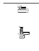
4WPB100, 4WPB1K PRT Bridge Terminal Input Modules 1. Function Terminal input modules connect directly to the datalogger's input terminals to provide completion resistors for resistive bridge measurements, voltage dividers, and precision current shunts. The 4WPB100 and 4WPB1K are used to provide completion resistors for 4 wire half bridge measurements of 100 Ohm and 1 killohm Platinum Resistance Thermometer (PRT), respectively. H L G H L AG H L AG FIGURE 1-1. Terminal Input Module 2.
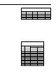
4WPB100, 4WPB1K PRT Bridge Terminal Input Modules Vx 10k 5% H HI Rf 0.01% Rf = 100 , 1k L LO HI Rs LO GND GND FIGURE 2-1. Circuit Schematic 3. Wiring The Terminal input module is connected to the appropriate channel. The dashed lines in Figure 2-1 indicate the sensor wiring. When making 4 wire half bridge measurements, the 4WPB is connected to a differential channel and the sense leads from the PRT to the next differential channel. The black excitation wire is connected to the excitation channel.
4WPB100, 4WPB1K PRT Bridge Terminal Input Modules TABLE 3-1. 4WPB100/4WPB1K Connections to Campbell Scientific Dataloggers Function Excitation V1 High V1 Low Ground Label/Lead Black Wire H L G CR10X, CR510 E1 1H 1L AG CR23X, CR1000, CR800, CR850, CR3000 EX1 1H 1L 21X, CR7, CR9000X Excitation 1 1H 1L 4. Programming Examples The following examples simply show the two instructions necessary to 1) make the measurement and 2) calculate the temperature.
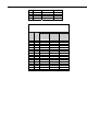
4WPB100, 4WPB1K PRT Bridge Terminal Input Modules 650 700 750 800 850 329.51 345.13 360.47 375.51 390.26 753 720 691 664 640 1507 1441 1382 1328 1280 TABLE 4-2. Excitation Voltage for 1000 Ohm PRT in 4WPB1000 Based on Maximum Temperature and Input Voltage Range Max. Temp. °C 50 100 150 200 250 300 350 400 450 500 550 600 650 700 750 800 850 4 PRT Resist. Ohms 1194. 1385. 1573.1 1758.4 1940.7 2120.2 2296.7 2470.4 2641.1 2809. 2973.9 3135.9 3295.1 3451.3 3604.7 3755.1 3902.
4WPB100, 4WPB1K PRT Bridge Terminal Input Modules 4.1 CR10(X) 01: Full Bridge w/mv Excit (P9) 1: 1 Reps 2: 23 ±25 mV 60 Hz Rejection Ex Range 3: 23 ±25 mV 60 Hz Rejection Br Range 4: 1 DIFF Channel 5: 1 Excite all reps w/Exchan 1 6: 2035 mV Excitation 7: 1 Loc [ Rs_Ro ] 8: 1.0 Mult 9: 0 Offset 02: Temperature RTD (P16) 1: 1 Reps 2: 1 R/Ro Loc [ Rs_Ro 3: 2 Loc [ Temp_C ] 4: 1 Mult 5: 0 Offset ] 4.
4WPB100, 4WPB1K PRT Bridge Terminal Input Modules 4.3 CR7 1: Full Bridge w/mv Excit (P9) 1: 1 Reps 2: 3 ± 15 mV Slow Range 3: 3 ± 15 mV Slow Range 4: 1 In Card 5: 1 DIFF Channel 6: 1 Ex Card 7: 1 Ex Channel 8: 1 Meas/Ex 9: 4070 mV Excitation 10: 1 Loc [ Rs_Ro ] 11: 1.0 Mult 12: 0.0 Offset 2: Temperature RTD (P16) 1: 1 Reps 2: 1 R/RO Loc [ Rs_Ro 3: 2 Loc [ Temp_C ] 4: 1.0 Mult 5: 0.0 Offset ] 4.
4WPB100, 4WPB1K PRT Bridge Terminal Input Modules 4.5 CR1000 'CR1000 Series Datalogger Public Rs_R0, Temp_C DataTable (Hourly,True,-1) DataInterval (0,60,Min,0) Average (1,Temp_C,IEEE4,0) EndTable BeginProg Scan (1,Sec,0,0) BrHalf4W (Rs_R0,1,mV25,mV25,1,Vx1,1,2035,True ,True ,0,250,1.0,0) PRT (Temp_C,1,Rs_R0,1.0,0) CallTable Hourly NextScan EndProg 5.
4WPB100, 4WPB1K PRT Bridge Terminal Input Modules The RTD Instruction (16) computes the temperature (°C) for a DIN 43760 standard PRT from the ratio of the PRT resistance at the temperature being measured (Rs) to its resistance at 0°C (R0). Thus, a multiplier of Rf/R0 is used with the 4 wire half bridge instruction to obtain the desired intermediate, Rs/R0 = (Rs/Rf x Rf/Ro). If Rf and R0 are equal, the multiplier is 1. The fixed resistor must be thermally stable.
4WPB100, 4WPB1K PRT Bridge Terminal Input Modules With the PRT at 0 °C, Rs=Ro. Thus, the above result becomes Ro/Rf, the reciprocal of the multiplier required to calculate temperature, Rf/R0. By making a measurement with the PRT in an ice bath, errors in both Rs and Ro. can be accounted for. To perform the calibration, connect the PRT to the datalogger and program the datalogger to measure the PRT with the 4 wire half bridge as shown in the example section (multiplier = 1).
4WPB100, 4WPB1K PRT Bridge Terminal Input Modules This is a blank page.
This is a blank page.
Campbell Scientific Companies Campbell Scientific, Inc. (CSI) 815 West 1800 North Logan, Utah 84321 UNITED STATES www.campbellsci.com info@campbellsci.com Campbell Scientific Africa Pty. Ltd. (CSAf) PO Box 2450 Somerset West 7129 SOUTH AFRICA www.csafrica.co.za cleroux@csafrica.co.za Campbell Scientific Australia Pty. Ltd. (CSA) PO Box 444 Thuringowa Central QLD 4812 AUSTRALIA www.campbellsci.com.au info@campbellsci.com.au Campbell Scientific do Brazil Ltda.