
User Manual


4WPB100, 4WPB1K PRT Bridge Terminal Input Modules
2
GND
HI
LO
Rf
GND
H
L
Rf = 100 , 1k
Vx
10k
5%
Rs
HI
LO
0.01%
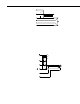
FIGURE 2-1. Circuit Schematic
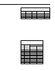
3. Wiring
The Terminal input module is connected to the appropriate channel. The
dashed lines in Figure 2-1 indicate the sensor wiring. When making 4 wire
half bridge measurements, the 4WPB is connected to a differential channel and
the sense leads from the PRT to the next differential channel. The black
excitation wire is connected to the excitation channel. In the followin g
examples the 4WPB is connected to differential channel 1 and the PRT to
differential channel 2; the excitation wire is connected to excitation chann el 1
(Figure 3-1).
Ex1
1H
1L
AG or
2H
2L
PRT
4WPB100
L
G
Datalogger
FIGURE 3-1. Wiring for Example Programs