INSTRUCTION MANUAL Use of the AVW1 and AVW4 with Geokon Model 4500 Vibrating Wire Piezometers and Pressure Transducers Revision: 1/92 C o p y r i g h t ( c ) 1 9 8 7 - 1 9 9 2 C a m p b e l l S c i e n t i f i c , I n c .
Warranty and Assistance The AVW1 AND AVW4 are warranted by CAMPBELL SCIENTIFIC, INC. to be free from defects in materials and workmanship under normal use and service for twelve (12) months from date of shipment unless specified otherwise. Batteries have no warranty. CAMPBELL SCIENTIFIC, INC.'s obligation under this warranty is limited to repairing or replacing (at CAMPBELL SCIENTIFIC, INC.'s option) defective products.
TABLE OF CONTENTS PDF viewers note: These page numbers refer to the printed version of this document. Use the Adobe Acrobat® bookmarks tab for links to specific sections. PAGE WARRANTY AND ASSISTANCE 1. GENERAL INFORMATION 1.1 Sensor Selection ..............................................................................................................................1-1 1.2 Sensor Care and Installation ........................................................................................................
TABLE OF CONTENTS TABLES 2.2-1 Temperature vs. Thermistor Resistance, V, oC, and Linearization Error ................................... 2-1 3.2-1 Calibration Data for Sensor 3998................................................................................................ 3-2 FIGURES 2.2-1 2.2-2 2.2-3 2.2-4 2.2-5 2.3-1 3.1-1 4.1-1 4.2-1 4.3-1 5.1-1 5.2-1 A.1 B.1-1 B.1-2 B.1-3 B.1-4 B.1-5 II Temperature Measurement Error at Three Temperatures as a Function of Lead Length .........
USE OF THE AVW1 AND AVW4 WITH GEOKON MODEL 4500 VIBRATING WIRE PIEZOMETERS AND PRESSURE TRANSDUCERS 1. GENERAL INFORMATION The CR10 is the only CSI datalogger that has the capability of measuring the vibrating wire pressure sensor in addition to the piezoresistive type of strain gage sensor. The CR10 can measure vibrating wire sensors with short leads without the AVW1 or AVW4.
AVW1/AVW4 be placed at the desired level and allowed to come to temperature equilibrium with its surroundings (5 minutes or more). The multiplier determined in equation 3.2-2 should be entered and 0.0 should be entered for the offset. After the temperature and the reading has stabilized, determine the value that would have to be added to the reading to obtain the measured level. Enter this value as the offset. In some cases there is no measured reference.
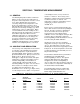
SECTION 2. TEMPERATURE MEASUREMENT 2.1 GENERAL The vibrating wire probe includes a thermistor which is used to measure the temperature of the probe. Probe temperature is used to correct errors in the vibrating wire measurement caused by changes in the temperature of the probe. The temperature correction is most important when the temperature of the medium the probe is measuring is changing (e.g. water temperature in a river or shallow lake).
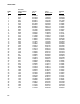
AVW1/AVW4 TEMP oC SENSOR RESISTANCE, OHMS VOLTS OUT CR10 OUTPUT,oC oC 0 1 2 3 4 5 6 7 8 9 10 11 12 13 14 15 16 17 18 19 20 21 22 23 24 25 26 27 28 29 30 31 32 33 34 35 36 37 38 39 40 41 42 43 44 45 46 47 48 9796 9310 8851 8417 8006 7618 7252 6905 6576 6265 5971 5692 5427 5177 4939 4714 4500 4297 4105 3922 3748 3583 3426 3277 3135 3000 287 2750 2633 2523 2417 2317 2221 2130 2042 1959 1880 1805 1733 1664 1598 1535 1475 1418 1363 1310 1260 1212 1167 0.791339 0.816459 0.841694 0.867031 0.892474 0.
AVW1/AVW4 TEMP oC SENSOR RESISTANCE, OHMS VOLTS OUT CR10 OUTPUT,oC oC 49 50 51 52 53 54 55 56 57 58 59 60 1123 1081 1040 1002 965 929.6 895.8 863.3 832.2 802.3 773.7 746.3 1.754878 1.765287 1.775568 1.785204 1.794687 1.803855 1.812697 1.821281 1.829571 1.837613 1.845372 1.852867 49.07873 50.08636 51.11067 52.09809 53.09674 54.08849 55.07032 56.04819 57.01651 57.97896 58.92977 59.86962 0.078734 0.086361 0.110677 0.098095 0.096746 0.088499 0.070322 0.048193 0.016519 -0.02103 -0.07022 -0.
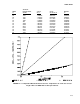
AVW1/AVW4 FIGURE 2.2-2. Temperature Measurement Error on a 1000 foot Lead. Wire is 22 AWG with 16 ohms per 1000 feet. FIGURE 2.2-3. Temperature Measurement Error on a 3000 foot Lead. Wire is 22 AWG with 16 ohms per 1000 feet.
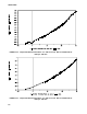
AVW1/AVW4 FIGURE 2.2-4. Temperature Measurement Error on a 5000 foot Lead. Wire is 22 AWG with 16 ohms per 1000 feet. FIGURE 2.2-5.
AVW1/AVW4 2.3 PROGRAMMING AND SENSOR HOOK-UP Measure the thermistor with Instruction 4 using a measurement range of 2500 mV fast, an excitation voltage of 2500 mV, a delay of 1, and a multiplier of 0.001. The resulting value is linearized with Instruction 55 using the following coefficients: C0 = -104.78, C1 = 378.11, C2 = 611.59, C3 = 544.27, C4 = -240.91, C5 = 43.089. The output is in degrees Celsius and covers the range from -5oC to +60oC.
SECTION 3. VIBRATING WIRE MEASUREMENT FIGURE 3.1-1. A Vibrating Wire Sensor 3.1 GENERAL Figure 3.1-1 illustrates how an increase in pressure on the diaphragm decreases the tension on the wire attached to the diaphragm. A decrease in the wire tension decreases the resonant frequency in the same way that loosening a string on a guitar decreases it's frequency. Therefore, the resonant frequency of the vibrating wire sensor decreases with increasing pressure.
AVW1/AVW4 TABLE 3.2-1. Calibration Data for Sensor 3998 Gage Factor Temp. Coeff. Zero Rdg. Period Temp. Baro. (psi/digit) 0.0151 (psi/oC) -0.0698 (digit) 9431 (usecond) 325.6 (oC) 24 (in Hg) 29.51 The equation to change the CR10's output into pressure (psi) exerted on the sensor is given below: P = [M * X] + B 3.2-1 where P is the pressure in psi and X is the result of measurement Instruction 28 in kHz2 ( = 1/T2 where T is the period in milliseconds).
AVW1/AVW4 Some additional information concerning the swept frequency may be found in Appendix C. NOTE: Please remember that sealed (or absolute) sensors calibrated near sea level will read negative at higher elevations due to the decrease in barometric pressure with increasing elevation. In most cases the solution is to load the sensor with extra external pressure to cause it to operate in its calibrated range.
AVW1/AVW4 Example: Using sensor number 3998 and assuming a sensor temperature of 15oC, the corrected pressure would be: Pt = P psi + (-0.0698 psi/oC)*(15oC - 24oC) = P psi + 0.6282 psi 3.6 DELAY BETWEEN MEASUREMENTS The vibrating wire sensor should not be excited more often than once every five time constants if high resolution is important. If more than one repetition is specified the "delay before excitation applied" parameter can be used to ensure the proper amount of delay between excitations.
SECTION 4. THE AVW1 4.1 GENERAL The AVW1 contains circuitry needed to interface Geokon's 4500 series vibrating wire sensor to the CR10. The AVW1 is designed to interface one vibrating wire sensor (temperature and pressure) to two single ended CR10 channels. The AVW1 has no quiescent current drain. The current drain during the very short (2.4 ms) temperature measurement is .4 mA or lower. The current drain during the vibrating wire measurement (170 ms to 500 ms) is 32 mA. The AVW1 is 2.5 inches long by 2.
AVW1/AVW4 water. The water depth above the sensor is referred to as the "Reading" in the following equation. The Reading decreases with increasing "Distance" from lip of well to water surface so the Distance is computed by subtracting the Reading from the Offset as shown in the above figure and the following equation. feet (of head above the sensor).
AVW1/AVW4 03: P28 01: 1 02: 2 03: 1 04: 24 05: 31 06: 500 07: 0000 08: 2 09: -15.1 10: 142.4 Vibrating Wire (SE) Rep IN Chan Excite all reps w/EXchan 1 Starting Freq. (units=100 Hz) End Freq. (units=100 Hz) No. of Cycles Rep delay (units=.01sec) Loc [:PRESS psi] Mult Offset 04: 01: 02: 03: P34 1 -24 4 Z=X+F X Loc TEMP C F calibration "Temp." in C Z Loc [:(T-To)*C] 05: 01: 02: 03: P37 4 -.0698 4 Z=X*F X Loc (T-To)*C F "Temp. Coeff.
AVW1/AVW4 This is a blank page.
SECTION 5. THE AVW4 5.1 GENERAL The AVW4 contains circuitry needed to interface Geokon's 4500 series vibrating wire sensor to the CR10. The AVW4 is designed to interface four vibrating wire sensors (temperature and pressure) to eight single ended CR10 channels. The AVW4 has no quiescent current drain. The current drain during the very short (2.4 ms) temperature measurement is .4 mA per channel or lower. The current drain during each vibrating wire measurement (170 ms to 500 ms) is 32 mA. The AVW4 is 6.
AVW1/AVW4 5.2 SENSOR HOOK UP FIGURE 5.2-1. Hook up for AVW4 5.3 DATALOGGER PROGRAMMING The following is a sample program that measures four sealed Geokon sensors and stores the temperature, pressure, pressure corrected for temperature, and barometric corrected pressure in psi in Input Locations 1..4, 5..8, 9..12, and 10..12 respectively. The example utilizes the calibration data given previously from sensor number 3998.
AVW1/AVW4 02: 01: 02: 03: 04: 05: 06: 07: 08: 09: P55 4 1 1 -104.78 378.11 -611.59 544.27 -240.91 43.089 Polynomial Reps X Loc TEMP C #1 F(X) Loc [:TEMP C #1] C0 C1 C2 C3 C4 C5 07: 03: 01: 02: 03: 04: 05: 06: 07: P28 4 5 1 24 31 500 500 08: 09: 10: 5 1 0 Vibrating Wire (SE) Reps IN Chan Excite all reps w/EXchan 1 Starting Freq. (units=100 Hz) End Freq. (units=100 Hz) No. of Cycles Rep delay (units=.
AVW1/AVW4 This is a blank page.
APPENDIX A.
This is a blank page.
APPENDIX B.
APPENDIX B.
APPENDIX B.
APPENDIX B.
APPENDIX B.
APPENDIX B. SCHEMATICS AND STUFFING CHARTS FOR AVW1 AND AVW4 This is a blank page.
APPENDIX C. THEORY AND ADDITIONAL DETAILS C.1 SWEPT FREQUENCY THEORY Example: f2 = 31 hundred Hz f1 = 24 hundred Hz X = (30*f1*f2)/(f2-f1) = 3189 where f1 and a f2 are the starting and ending frequencies in hundreds of Hz respectively. One clock cycle (CC) occurs every 813.8 ns or at a rate of 1.2288 mHz. Rule #1: 65535 > X > 256 the 256 constraint is somehow due to an 8 bit constraint. The 65535 constraint is some limit where the swept frequency can no longer be done in exactly 15 ms.
This is a blank page.
This is a blank page.
Campbell Scientific Companies Campbell Scientific, Inc. (CSI) 815 West 1800 North Logan, Utah 84321 UNITED STATES www.campbellsci.com info@campbellsci.com Campbell Scientific Africa Pty. Ltd. (CSAf) PO Box 2450 Somerset West 7129 SOUTH AFRICA www.csafrica.co.za sales@csafrica.co.za Campbell Scientific Australia Pty. Ltd. (CSA) PO Box 444 Thuringowa Central QLD 4812 AUSTRALIA www.campbellsci.com.au info@campbellsci.com.au Campbell Scientific do Brazil Ltda.