BlackGlobe Temperature Sensor for Heat Stress Revision: 9/13 C o p y r i g h t © 2 0 1 3 C a m p b e l l S c i e n t i f i c , I n c .
Warranty “PRODUCTS MANUFACTURED BY CAMPBELL SCIENTIFIC, INC. are warranted by Campbell Scientific, Inc. (“Campbell”) to be free from defects in materials and workmanship under normal use and service for twelve (12) months from date of shipment unless otherwise specified in the corresponding Campbell pricelist or product manual. Products not manufactured, but that are re-sold by Campbell, are warranted only to the limits extended by the original manufacturer.
Assistance Products may not be returned without prior authorization. The following contact information is for US and international customers residing in countries served by Campbell Scientific, Inc. directly. Affiliate companies handle repairs for customers within their territories. Please visit www.campbellsci.com to determine which Campbell Scientific company serves your country. To obtain a Returned Materials Authorization (RMA), contact CAMPBELL SCIENTIFIC, INC., phone (435) 227-9000.
Table of Contents PDF viewers: These page numbers refer to the printed version of this document. Use the PDF reader bookmarks tab for links to specific sections. 1. Introduction .................................................................1 2. Cautionary Statements...............................................1 3. Initial Inspection .........................................................1 3.1 Ships With List.....................................................................................1 4.
Table of Contents Appendices A. The Theory of BlackGlobe Temperature and Heat Stress ............................................................A-1 B. Edlog Programming Examples ..............................B-1 B.1 B.2 Example CR10X Program............................................................... B-1 Edlog Programming for Long Lead Lengths................................... B-9 5-1. 5-2. 6-1. 6-2. 6-3. 6-4. 6-5. Polynomial error curve (Edlog dataloggers only)................................
BlackGlobe Temperature Sensor for Heat Stress 1. Introduction The BlackGlobe Temperature Sensor for Heat Stress (BlackGlobe) measure radiant temperature. This measurement, along with the measurement of ambient air and wet-bulb temperatures, is used to calculate the wet-bulb globe temperature (WBGT). The WBGT index combines the effects of temperature, humidity, radiant heat, and wind into one single index employed to express environmental heat stress.
BlackGlobe Temperature Sensor for Heat Stress 4. Overview The BlackGlobe uses a thermistor inside a 15.24 cm (6 in) hollow copper sphere, painted black to measure radiant temperature. This measurement along with the measurement of ambient air and wet-bulb temperatures may be used to calculate the WBGT index, which is sometimes referred to as the Humidex. Sensor cable length is specified at the time of order. Do not exceed 1000 feet of cable.
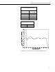
BlackGlobe Temperature Sensor for Heat Stress TABLE 5-1. Thermistor Interchangeability Specification Temperature (°C) Temperature Tolerance (±°C) −5 0.14 0 to +70 0.10 +85 0.25 +95 0.35 TABLE 5-2. Polynomial Error –5° to +95° < ±0.5°C –3° to +90° < ±0.1°C FIGURE 5-1.
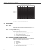
BlackGlobe Temperature Sensor for Heat Stress Thermistor Interchangeability Limits 0.3 0.25 0.2 0.15 0.1 0.05 Terror_therm_pos Terror_therm_neg 0 -0.05 -0.1 -0.15 -0.2 -0.25 -0.3 -5 10 25 40 55 70 85 100 T FIGURE 5-2. Thermistor interchangeability limits 6. Installation 6.1 Siting The BlackGlobe must be mounted in a location that will not be shadowed and is representative of the environmental conditions to be measured. 6.
BlackGlobe Temperature Sensor for Heat Stress Mounting Arm Pipe Clamp Slot Nuts Lock Washers Pipe Clamps U-bolt Mounting Bolt FIGURE 6-1. Mounting kit components 1. Place the mounting bolt through the hole in the mounting arm as shown in FIGURE 6-2. 2. Slide one of the lock washers against the mounting arm. 3. Thread both nuts about half way down the bolt and then slide on the last lock washer. The hardware should be arranged as shown in FIGURE 6-2. FIGURE 6-2.
BlackGlobe Temperature Sensor for Heat Stress 4. Tighten down the nut closest to the mounting arm so the bolt is held firmly in place. 5. Thread the BlackGlobe fitting onto the bolt. Thread it as far down as it will go, but you may have to back it off a bit. The cable gland and cable should align with the mounting arm as shown in FIGURE 6-3. 6. Tighten down the nut closest to the BlackGlobe fitting. The BlackGlobe and mounting bolt should not move when the all the hardware is tightened down.
BlackGlobe Temperature Sensor for Heat Stress FIGURE 6-4. BlackGlobe mounted to a crossarm (front view) FIGURE 6-5. BlackGlobe mounted to a crossarm (back view) 7. Operation 7.1 Wiring The wiring diagram for the BlackGlobe to a Campbell Scientific datalogger is given in TABLE 7-1. Temperature is measured with one single-ended input channel and a voltage excitation channel.
BlackGlobe Temperature Sensor for Heat Stress TABLE 7-1. Wiring Diagram for Campbell Scientific Dataloggers 7.2 CR800 CR850 CR5000 CR3000 CR1000 CR9000(X) CR510 CR500 CR10(X) 21X CR7 CR23X Color Description Black Voltage Excitation Switched Voltage Excitation Switched Excitation Switched Excitation Red Temperature Signal Single-Ended Input Single-Ended Input Single-Ended Input Purple Signal Ground AG Clear Shield G Calculations 7.2.
BlackGlobe Temperature Sensor for Heat Stress The equation is an inverse of a version of Teten’s equation (Tetens, 1930), optimized for dewpoints in the range –35° to 50°C, and is accurate to within plus or minus 0.1°C within that range. 7.2.3 Vapor Pressure Vapor pressure is calculated by the datalogger using Equation 3. P = RH*Psw/100 (3) where RH = relative humidity (%) Psw = saturation vapor pressure (kPa) over water 7.2.
BlackGlobe Temperature Sensor for Heat Stress 7.2.6 Mean Site Barometric Pressure Calculation (SP_kPa) The wet-bulb instruction needs mean barometric pressure which is closely related to elevation of the site. U.S. Standard Atmosphere and dry air were assumed when Equation 6 was derived (Wallace & Hobbes, 1977). 5.25328 ⎫ ⎧⎪ ⎛ E ⎞ ⎪ SPkPa = 101.325 − 101.325⎨1 − ⎜1 − ⎟ ⎬ 44307 . 69231 ⎠ ⎪⎭ ⎪⎩ ⎝ (6) The value of SPkPa is in kilopascals and the site elevation, E, is in meters.
BlackGlobe Temperature Sensor for Heat Stress Dim Dim Dim Dim Dim UpperTmp LowerTmp old_wbT, new_wbT WB_VP_kPa, Diff_VP_kPa Diff_wbT 'Define Data Tables 'Hourly data table. DataTable (Hourly,1,-1) DataInterval (0,1,Hr,10) Average (1,AirTempC,FP2,False) Sample (1,AirRH,FP2) Average (1,DewPnt_C,FP2,False) Average (1,WetBlb_C,FP2,False) Average (1,WBGT_C,FP2,False) EndTable 'Daily datalogger status table.
BlackGlobe Temperature Sensor for Heat Stress 7.4 Long Lead Lengths If the BlackGlobe has lead lengths greater than 300 feet, a longer settling time before the measurement is made is required. For CRBasic loggers, the 60 and 50 Hz integration options include a 3 ms settling time; longer settling times also can be entered into the Settling Time parameter. In Edlog, use the DC Half Bridge Instruction (Instruction 4) with a 2 ms delay to measure the temperature. CAUTION 8.
Appendix A. The Theory of BlackGlobe Temperature and Heat Stress The Wet-Bulb Globe Temperature Index (WBGT) combines the effects of temperature, humidity, radiant heat, and wind into one single index employed to express environmental heat stress. Loss of physical and mental efficiency occurs under definable degrees of heat stress. Severe heat stress can lead to fatigue, exhaustion and possibly even disability or death.
Appendix A.
Appendix B. Edlog Programming Examples B.1 Example CR10X Program Instruction 5 (AC Half Bridge) is used to measure the thermistor probe inside the sphere. Instruction 55 (Polynomial) is used to calculate the temperature in degrees Celsius. The polynomial coefficients are shown in TABLE B-1. Thermistor resistance and computed temperature over a –10 to +84°C range is shown in TABLE B-2. The example includes instructions for measuring an HC2S3 to supply air temperature and relative humidity values.
Appendix B.
Appendix B. Edlog Programming Examples ;Dewpoint calculation. 15: Z=X*F (P37) 1: 10 X Loc [ VP_kPa ] 2: 1.63725 F 3: 20 Z Loc [ scratch1 ] 16: Z=LN(X) (P40) 1: 20 X Loc [ scratch1 ] 2: 20 Z Loc [ scratch1 ] 17: Z=X*F (P37) 1: 20 X Loc [ scratch1 ] 2: 241.88 F 3: 21 Z Loc [ scratch2 ] 18: Z=F x 10^n (P30) 1: 17.
Appendix B. Edlog Programming Examples 26: Z=X (P31) 1: 7 2: 15 X Loc [ DewPnt_C ] Z Loc [ LowerTmp ] ;Iterative loop to figure out wet-bulb temperature. 27: Beginning of Loop (P87) 1: 0 Delay 2: 25 Loop Count 28: Z=X (P31) 1: 12 2: 11 X Loc [ new_wbT ] Z Loc [ old_wbT ] 29: Z=X-Y (P35) 1: 14 X Loc [ UpperTmp ] 2: 15 Y Loc [ LowerTmp ] 3: 12 Z Loc [ new_wbT ] 30: Z=X*F (P37) 1: 12 X Loc [ new_wbT ] 2: 0.
Appendix B. Edlog Programming Examples 37: Z=X (P31) 1: 12 2: 14 X Loc [ new_wbT ] Z Loc [ UpperTmp ] 38: Else (P94) 39: Z=X (P31) 1: 12 2: 15 X Loc [ new_wbT ] Z Loc [ LowerTmp ] 40: End (P95) 41: If (X<=>F) (P89) 1: 16 X Loc [ Diff_wbT ] 2: 4 < 3: 0.01 F 4: 31 Exit Loop if True 42: End (P95) ;Wet-bulb temperature. 43: Z=X (P31) 1: 12 2: 8 X Loc [ new_wbT ] Z Loc [ WetBlb_C ] ;Calculate Wet-Bulb Globe (HUMIDEX) temperature. 44: Z=X*F (P37) 1: 4 X Loc [ AirTempC ] 2: 0.
Appendix B.
Appendix B. Edlog Programming Examples 62: Maximum (P73) 1: 1 Reps 2: 0 Value Only 3: 2 Loc [ CR10XTmpC ] 63: Minimum (P74) 1: 1 Reps 2: 0 Value Only 3: 2 Loc [ CR10XTmpC ] *Table 2 Program 01: 0 Execution Interval (seconds) *Table 3 Subroutines End Program TABLE B-1. Polynomial Coefficients Coefficient Value C0 –26.97 C1 69.635 C2 –40.66 C3 16.573 C4 –3.455 C5 0.301 TABLE B-2. Actual Temperature, Sensor Resistance, and Computed Temperature Temperature °C Resistance OHMS Output °C –10.
Appendix B. Edlog Programming Examples TABLE B-2. Actual Temperature, Sensor Resistance, and Computed Temperature B-8 Temperature °C Resistance OHMS Output °C 10.00 207807 10.00 12.00 187803 12.04 14.00 169924 14.07 16.00 153923 16.09 18.00 139588 18.10 20.00 126729 20.09 22.00 115179 22.07 24.00 104796 24.05 26.00 95449 26.02 28.00 87026 27.99 30.00 79428 29.97 32.00 72567 31.94 34.00 66365 33.93 36.00 60752 35.93 38.00 55668 37.93 40.00 51058 39.94 42.
Appendix B. Edlog Programming Examples TABLE B-2. Actual Temperature, Sensor Resistance, and Computed Temperature Temperature °C Resistance OHMS Output °C 74.00 13405 73.98 76.00 12479 75.99 78.00 11625 78.01 80.00 10837 80.02 82.00 10110 82.03 84.00 9438.1 84.04 86.00 8816.9 86.03 88.00 8241.9 88.00 90.00 7709.7 89.96 92.00 7216.3 91.89 94.00 6758.9 93.80 96.00 6334.5 95.67 98.00 5940.5 97.51 100.00 5574.3 99.31 B.
Appendix B. Edlog Programming Examples 02: Polynomial (P55) 1: 1 Reps 2: 1 X Loc [BGTemp_C ] ; 3: 1 F(X) Loc [BGTemp_C ] 4: -26.97 C0 5: 69.635 C1 6: -40.66 C2 7: 16.573 C3 8: -3.455 C4 9: .
Campbell Scientific Companies Campbell Scientific, Inc. (CSI) 815 West 1800 North Logan, Utah 84321 UNITED STATES www.campbellsci.com • info@campbellsci.com Campbell Scientific Africa Pty. Ltd. (CSAf) PO Box 2450 Somerset West 7129 SOUTH AFRICA www.csafrica.co.za • cleroux@csafrica.co.za Campbell Scientific Australia Pty. Ltd. (CSA) PO Box 8108 Garbutt Post Shop QLD 4814 AUSTRALIA www.campbellsci.com.au • info@campbellsci.com.au Campbell Scientific do Brasil Ltda. (CSB) Rua Apinagés, nbr.