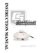
CMP6-L, CMP11-L, and CMP21-L Pyranometers Revision: 9/13 C o p y r i g h t © 2 0 0 6 - 2 0 1 3 C a m p b e l l S c i e n t i f i c , I n c .
Warranty “PRODUCTS MANUFACTURED BY CAMPBELL SCIENTIFIC, INC. are warranted by Campbell Scientific, Inc. (“Campbell”) to be free from defects in materials and workmanship under normal use and service for twelve (12) months from date of shipment unless otherwise specified in the corresponding Campbell pricelist or product manual. Products not manufactured, but that are re-sold by Campbell, are warranted only to the limits extended by the original manufacturer.
Assistance Products may not be returned without prior authorization. The following contact information is for US and international customers residing in countries served by Campbell Scientific, Inc. directly. Affiliate companies handle repairs for customers within their territories. Please visit www.campbellsci.com to determine which Campbell Scientific company serves your country. To obtain a Returned Materials Authorization (RMA), contact CAMPBELL SCIENTIFIC, INC., phone (435) 227-9000.
Table of Contents PDF viewers: These page numbers refer to the printed version of this document. Use the PDF reader bookmarks tab for links to specific sections. 1. Introduction .................................................................1 2. Cautionary Statements...............................................1 3. Initial Inspection .........................................................1 3.1 3.2 Ships With............................................................................................
Table of Contents 8. Maintenance ..............................................................22 8.1 8.2 8.3 8.4 Cleaning Domes ................................................................................ 23 Changing the Desiccant..................................................................... 23 Check Sensor Output......................................................................... 24 Recalibration ..................................................................................... 24 9.
Table of Contents 7-4. 7-5. 7-6. 7-7. 7-8. 7-9. A-1. CMP21 Single-Ended Connections to Campbell Scientific Dataloggers.....................................................................................14 Multipliers Required for Flux Density and Total Fluxes ...................15 CR1000 Wiring for CMP6 Example Program ...................................17 CR1000 Wiring for CMP11 Example Program .................................18 CR1000 Wiring for CMP21 Example Program .................................
Table of Contents iv
CMP6-L, CMP11-L, and CMP21-L Pyranometers 1. Introduction CMP-series pyranometers are designed for continuous outdoor monitoring of solar radiation intensity. A flat spectral sensitivity from 285 to 2800 nm enables accurate measurements in natural sunlight, under plant canopies, and in green houses or buildings. When inverted, these pyranometers can measure reflected solar radiation. Uses include monitoring global horizontal irradiance (GHI) and plane of array irradiance (POA).
CMP6-L, CMP11-L, and CMP21-L Pyranometers 3.1 Ships With (2) Bolts for mounting from original mfg (1) Instruction Manual from original mfg (1) Sun Shield from original mfg (2) Nylon washers from original mfg 3.2 Calibration Certificate Each pyranometer is shipped with an instruction manual provided by Kipp & Zonen that contains information concerning its construction, spectral sensitivity, cosine response, and a simple sensor check out procedure.
CMP6-L, CMP11-L, and CMP21-L Pyranometers 4.2 Mounting See Section 7.1, Mounting to a Tripod Tower, for more information. FIGURE 4-1. Pyranometer installation CM245 Adjustable Angle Mounting Stand CM2XX-Series Crossarm FIGURE 4-2.
CMP6-L, CMP11-L, and CMP21-L Pyranometers FIGURE 4-3. Two views of a pyranometer mounted at an angle for the Northern Hemisphere FIGURE 4-4.
CMP6-L, CMP11-L, and CMP21-L Pyranometers 4.3 Datalogger Programming / Wiring The simplest method for programming the datalogger to measure a CMP6 or CMP11 is to use Campbell Scientific's SCWin Short Cut Program Generator (see FIGURE 4-5). Wire the pyranometer according to the wiring diagram generated by Short Cut. NOTE The CMP21 is not included in Short Cut. Refer to Section 7, Installation, for wiring and programming information if not using Short Cut. FIGURE 4-5.
CMP6-L, CMP11-L, and CMP21-L Pyranometers 5. Overview 5.1 Models CMP-series models differ in accuracy and performance. See Section 6, Specifications. The CMP21 also includes an internal thermistor allowing individually optimized compensation of the measurements. The –L portion of the model number indicates that the pyranometer has a user-specified cable length. The pyranometers have several cable termination options. Their cables can terminate in: • • • 5.
CMP6-L, CMP11-L, and CMP21-L Pyranometers 6. Specifications 6.1 Pyranometers TABLE 6-1.
CMP6-L, CMP11-L, and CMP21-L Pyranometers FIGURE 6-1. Dimensions of the CMP6, CMP11, and CMP21 6.2 CVF3 Ventilation Unit Compatible Pyanometers: CMP6, CMP11, CMP21 Power supply: 12 Vdc, 1.3 A (with 10 W Heater) Operating temperature range: –40° to 70°C Ventilation power: 5 W continuously Heating power: 5 W and 10 W Heater induced offset: <1 W•m–2 (with CMP11 Pyranometer) Weight without cable: 1.6 kg (3.5 lb) FIGURE 6-2.
CMP6-L, CMP11-L, and CMP21-L Pyranometers 7. Installation 7.1 Mounting to a Tripod or Tower Tools required for installation on a tripod or tower: Small and medium Phillips screwdrivers 5/16”, 1/2” open end wrenches 5/32” Allen wrench Tape measure UV-resistant wire ties Side-cut pliers Compass Step ladder The pyranometers include a bubble level and two leveling screws, which allow them to be leveled horizontally without using a leveling base. They mount to a mast, crossarm, or pole (1.0 in. to 2.1 in.
CMP6-L, CMP11-L, and CMP21-L Pyranometers First 1.5” u-bolt 40 Second 1.5” u-bolt FIGURE 7-2. CM245 bracket with 1.5” u-bolts positioned to mount pyranometer at a 40° angle on a vertical pipe Do the following to level the pyranometer horizontally (see FIGURE 7-3): 1. Attach the mounting stand to the crossarm. 2. Loosely mount the pyranometer on the mounting stand. Do not fully tighten the two mounting screws. 3. Turn the leveling screws as required to bring the bubble of the level within the ring. 4.
CMP6-L, CMP11-L, and CMP21-L Pyranometers Sun shield Mounting screws Nylon washers Bubble level Pyranometer Levelling screw CM245 mounting stand Crossarm FIGURE 7-3. Exploded view of the pyranometer mounting 7.2 Wiring NOTE Short Cut users should wire the sensor according to the wiring diagram generated by Short Cut. The cable of the CMP6 and CMP11 has two conductors and a shield. The cable of the CMP21 has five conductors and a shield.
CMP6-L, CMP11-L, and CMP21-L Pyranometers 7.2.1 CMP6, CMP11, and CMP21 Thermopile Schematic A schematic diagram of a CMP6, CMP11, or CMP21 thermopile is shown in FIGURE 7-4. WRed hite (+) Black Blue (-) Black Shield FIGURE 7-4. CMP6, CMP11, and CMP21 thermopile detector schematic 7.2.2 CMP6 and CMP11 Wiring NOTE A CMP6 or CMP11 purchased from Campbell Scientific has different wiring than a pyranometer purchased directly from Kipp & Zonen.
CMP6-L, CMP11-L, and CMP21-L Pyranometers TABLE 7-2. CMP6 and CMP11 Single-Ended Connections to Campbell Scientific Dataloggers Color Description CR9000(X), CR5000, CR3000, CR1000, CR800 White Signal (+) SE Analog Black Signal (–) AG Clear Shield G CR510, CR500, CR10(X) 21X, CR7, CR23X SE Analog SE Analog 7.2.3 CMP21 Wiring NOTE A CMP21 purchased from Campbell Scientific has different wiring than a CMP21 purchased directly from Kipp & Zonen.
CMP6-L, CMP11-L, and CMP21-L Pyranometers TABLE 7-4.
CMP6-L, CMP11-L, and CMP21-L Pyranometers 7.3.1.1 Input Range The output voltage is usually between 5 and 20 mV per 1000 W•m–2. When estimating the maximum likely value of sensor output a maximum value of solar radiation of 1100 W•m–2 can be used for field measurements on a horizontal surface. Plane of array irradiances can exceed 1500 W•m–2. Select the input range as follows: 1.
CMP6-L, CMP11-L, and CMP21-L Pyranometers 7.3.1.3 Offset The offset will normally be fixed at zero as the sensor should output no significant signal in dark conditions. In practice, because of the nature of thermopile detector sensors, there will be some offset in dark conditions; sometimes this offset can give negative light readings. This offset varies with several factors (e.g., rate of change of sensor temperature), so it cannot be removed with a fixed offset.
CMP6-L, CMP11-L, and CMP21-L Pyranometers Where, Vx = the value provided by the half bridge instruction In CRBasic, the conversion to resistance is entered as a mathematical expression. In Edlog, Instruction P59 (Bridge Transform) does the conversion. The Steinhart-Hart equation is used to convert resistance to temperature. The Steinhart-Hart equation for converting resistance to degree Celsius is as follows: Temperature = 1/[A + B*LN(resistance) + C*(LN(resistance))^3] - 273.
CMP6-L, CMP11-L, and CMP21-L Pyranometers 'CR1000 Series Datalogger Public PTemp Public Batt_Volt Public CMP6_Irr Units CMP6_Irr = W/m2 DataTable (TenMin,1,-1) DataInterval (0,1,Min,4) Minimum (1,Batt_Volt,FP2,0,False) Sample (1,PTemp,FP2) Average (1,CMP6_Irr,FP2,False) StdDev (1,CMP6_Irr,FP2,False) EndTable BeginProg Scan (1,Sec,0,0) 'Measure the Battery Voltage and Panel Temperature PanelTemp (PTemp,250) Battery (Batt_Volt) 'Measure the CMP6 VoltDiff (CMP6_Irr,1,mV25C,1,True ,10000,_60Hz,1000/14.
CMP6-L, CMP11-L, and CMP21-L Pyranometers 'CR1000 Series Datalogger Public PTemp Public Batt_Volt Public CMP11_Irr Units CMP11_Irr = W/m2 DataTable (TenMin,1,-1) DataInterval (0,1,Min,4) Minimum (1,Batt_Volt,FP2,0,False) Sample (1,PTemp,FP2) Average (1,CMP11_Irr,FP2,False) StdDev (1,CMP11_Irr,FP2,False) EndTable BeginProg Scan (1,Sec,0,0) 'Measure the Battery Voltage and Panel Temperature PanelTemp (PTemp,250) Battery (Batt_Volt) 'Measure the CMP11 VoltDiff (CMP11_Irr,1,mV25C,2,True ,10000,_60Hz,1000/8.
CMP6-L, CMP11-L, and CMP21-L Pyranometers 'CR1000 Series Datalogger Public PTemp Public Batt_Volt Public CMP21_Irr Public CMP21_T_C Public CMP21_T_K Dim Rs,Vs_Vx Units CMP21_Irr = W/m2 Units CMP21_T_C = Degrees C Units CMP21_T_K = Degrees K DataTable (TenMin,1,-1) DataInterval (0,1,Min,8) Minimum (1,Batt_Volt,FP2,0,False) Sample (1,PTemp,FP2) Average (1,CMP21_Irr,FP2,False) StdDev (1,CMP21_Irr,FP2,False) Average (1,CMP21_T_C,FP2,False) StdDev (1,CMP21_T_C,FP2,False) Average (1,CMP21_T_K,FP2,False) StdDev (
CMP6-L, CMP11-L, and CMP21-L Pyranometers Wiring for the example is given in TABLE 7-9. TABLE 7-9. CR10X Wiring for CMP6 Example Program Wire Color Description CR10X White Solar Signal (+) 1H Black Solar Signal (–) 1L Clear Shield AG Jumper* * Jumper 1L to AG terminal on CR10X with user-supplied 26 AWG or larger wire. ;{CR10X} *Table 1 Program 01: 10.0000 Execution Interval (seconds) ; CMP6 measurement in W/m2 1: Volt (Diff) (P2) 1: 1 2: 23 3: 1 4: 3 5: 69.
CMP6-L, CMP11-L, and CMP21-L Pyranometers 7: Set Active Storage Area (P80) 1: 1 Final Storage Area 1 2: 101 Array ID 8: Real Time (P77) 1: 1220 Year,Day,Hour/Minute (midnight = 2400) 9: Average (P71) 1: 1 Reps 2: 3 Loc [ Solar_Wm2 ] 10: If time is (P92) 1: 0 Minutes (Seconds --) into a 2: 1440 Interval (same units as above) 3: 10 Set Output Flag High (Flag 0) 11: Set Active Storage Area (P80) 1: 1 Final Storage Area 1 2: 102 Array ID 12: Real Time (P77) 1: 1220 Year,Day,Hour/Minute (midnight = 2400) 13: Re
CMP6-L, CMP11-L, and CMP21-L Pyranometers 8.1 Cleaning Domes Clean the outer dome at regular intervals (e.g., every week or so). Remove any accumulated dust, condensation, or ice from the dome and pyranometer body using a soft cloth dampened with water or alcohol (see FIGURE 8-1). FIGURE 8-1. Reading is reduced if dome is not dry or clean 8.
CMP6-L, CMP11-L, and CMP21-L Pyranometers FIGURE 8-2. Changing the desiccant 8.3 Check Sensor Output It is also important to check the data returned from the sensor as it will show the first indication of a fault. When doing this you should be aware of several expected phenomena that can cause strange measurements.
CMP6-L, CMP11-L, and CMP21-L Pyranometers 9. Troubleshooting Symptom: NAN, –9999, or radiation values around 0 1. Check that the sensor is wired to the differential channel specified by the measurement instruction. 2. Verify that the range code is correct for the datalogger type. 3. Measure the impedance across the red and blue sensor wires. This should be around 100 ohms plus the cable resistance (typically 0.1 ohm•m–1). If the resistance is very low, there may be a short circuit (check the wiring).
CMP6-L, CMP11-L, and CMP21-L Pyranometers 26
Appendix A. CVF3 Heater/Ventilator A.1 General Information The CVF3 consists of a ventilation unit and heaters. The ventilation unit uses a fan and inlet filter to draw clean air over the pyranometer’s domes. The fan runs continuously to reduce dust and dirt settling, to dissipate rain drops, and to stabilize the dome temperature. The CVF3 has both a 5 W and a 10 W heater. The 5 W heater raises the temperature of the dome slightly above ambient temperature to prevent the formation of dew and frost.
Appendix A. CVF3 Heater/Ventilator A.3 CVF3 Installation The CVF3 heater/ventilator unit includes the heater/ventilator unit, white cover, cable, and mounting hardware. Tools required for mounting to a tripod or tower are: • Small and medium Phillips screwdrivers • 5/16”, 1/2” open end wrenches • 5/32” Allen wrench • Tape measure • UV-resistant wire ties • Side-cut pliers • Compass • Step ladder To install, do the following: 1. Remove leveling screws from the pyranometer. 2.
Appendix A. CVF3 Heater/Ventilator 4. Loosely mount the pyranometer on the 27084 mounting stand. Do not fully tighten the two mounting screws. 5. Turn the CVF3’s leveling screws bringing the bubble of the pyranometer’s level within the ring (see FIGURE A-3). FIGURE A-3. CVF3 installed onsite 6. Tighten the mounting screws to secure the assembly in its final position. Check that the pyranometer is still correctly leveled and adjust as necessary. 7.
Appendix A. CVF3 Heater/Ventilator FIGURE A-4. Fastening cover on CVF3 8. Attach the power cable to the CVF3 connector. A.4 Wiring Wiring of the CVF3 is shown in TABLE A-1. Refer to Section 7.2, Wiring, for information about wiring the pyranometer. TABLE A-1.
Appendix A. CVF3 Heater/Ventilator A.5 CVF3 Heater/Ventilator Maintenance 1. Refer to Section 8, Maintenance, for the pyranometer’s maintenance. 2. Inspect the area directly under the 120 mm diameter hole in the mounting plate to ensure that it is free from leaves, snow, or other obstructions that can inhibit air flow. 3. Unclip the CVF3’s filter cover and check the filters (see FIGURE A-5). 4. Replace filters as needed. FIGURE A-5.
Appendix A.
Campbell Scientific Companies Campbell Scientific, Inc. (CSI) 815 West 1800 North Logan, Utah 84321 UNITED STATES www.campbellsci.com • info@campbellsci.com Campbell Scientific Africa Pty. Ltd. (CSAf) PO Box 2450 Somerset West 7129 SOUTH AFRICA www.csafrica.co.za • cleroux@csafrica.co.za Campbell Scientific Australia Pty. Ltd. (CSA) PO Box 8108 Garbutt Post Shop QLD 4814 AUSTRALIA www.campbellsci.com.au • info@campbellsci.com.au Campbell Scientific do Brasil Ltda. (CSB) Rua Apinagés, nbr.