CS10-L and CS15-L Current Transformers Revision: 3/12 C o p y r i g h t © 2 0 0 1 - 2 0 1 2 C a m p b e l l S c i e n t i f i c , I n c .
Warranty “PRODUCTS MANUFACTURED BY CAMPBELL SCIENTIFIC, INC. are warranted by Campbell Scientific, Inc. (“Campbell”) to be free from defects in materials and workmanship under normal use and service for twelve (12) months from date of shipment unless otherwise specified in the corresponding Campbell pricelist or product manual. Products not manufactured, but that are re-sold by Campbell, are warranted only to the limits extended by the original manufacturer.
Assistance Products may not be returned without prior authorization. The following contact information is for US and international customers residing in countries served by Campbell Scientific, Inc. directly. Affiliate companies handle repairs for customers within their territories. Please visit www.campbellsci.com to determine which Campbell Scientific company serves your country. To obtain a Returned Materials Authorization (RMA), contact CAMPBELL SCIENTIFIC, INC., phone (435) 227-9000.
CS10-L and CS15-L Table of Contents PDF viewers: These page numbers refer to the printed version of this document. Use the PDF reader bookmarks tab for links to specific sections. 1. General Description.....................................................1 2. Specifications ..............................................................1 3. Installation....................................................................2 4. Wiring............................................................................
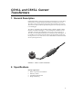
CS10-L and CS15-L Current Transformers 1. General Description Campbell Scientific’s CS10 and CS15 detect and measure the ac current along an electrical wire using the magnetic field that is generated by that current. The CS10 or the CS15 do not have direct electrical connection to the system. These sensors output a millivolt signal allowing them to be directly connected to our dataloggers. The CS10 is compatible with our CR800, CR850, CR1000, CR3000, CR510, CR10(X), and CR23X dataloggers.
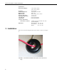
CS10-L and CS15-L Current Transformers Specifications Measurement Ranges: Frequency: Insulation Resistance: High Potential: Rated Current: Storage Temperature: Operating Temperature: Case Material: Construction: Accuracy with 10 ohm burden max. (resistive): Dimensions: 0.15 to 200 A (CS10) 0.
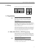
CS10-L and CS15-L Current Transformers 4. Wiring The CS10-L and CS15-L use a single-ended analog channel as follows. CS10-L CS15-L White Single-Ended Channel Red EX Black AG or White SE Shield AG or Black Shield 5. Programming NOTE SCWIN users: This manual was written primarily for those whose needs are not met by SCWin. Your procedure is much simpler: just add the CS10-L or CS15 (in the Miscellaneous Sensors folder), save your program, and follow the wiring shown in Step 2 of SCWin.
CS10-L and CS15-L Current Transformers CAUTION Do not average the waveform or use 60 Hz (or 50 Hz) rejection. Under these circumstances, the amperage value will always be zero. Below is an example CR1000 program. In the program, a multiplier of 0.2 is applied to the RMS value; see Section A.4 for more information.
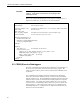
CS10-L and CS15-L Current Transformers 25 Samples of Amperage on CR200(X) Datalogger (60 Hz) or 30 Samples of Amperage on CR200(X) Datalogger (50 Hz) 80 60 40 mV 20 CS15-L waveform 0 -20 1 3 5 7 9 11 13 15 17 19 21 23 25 -40 -60 -80 Instanteneous Amps FIGURE 3. Graph of a CS15 waveform CR200(X) Program for 60 Hz 'CR200(X) Series Datalogger ' Program name: CS15-LManual.
CS10-L and CS15-L Current Transformers CallTable Test NextScan EndProg CR200(X) Program for 50 Hz ' CR200(X) Series Datalogger ' Program name: CS15-LManual.cr2 ' date: 4 Mar 2009 ' program author: Brad Maxfield Const Samples = 30 'Const Samples = 25 Public Crnt_A Public mV(Samples) Dim Counter ' 30 samples for 2 waves of 50 Hz. ' 25 samples for 2 waves of 60 Hz.
CS10-L and CS15-L Current Transformers Remember that it is important to get complete cycles. For Instruction 23, if parameters 5 and 6 are 2.0 and 0.05, respectively, then you get five complete cycles for a 50-Hz waveform, and six complete cycles for a 60-Hz waveform (see Figure 4). The multiplier for the CS10 is 0.2; see Section A.4 for more information. Six Cycles at 60 Hz Burst CR10X I Instanteneous FIGURE 4.
CS10-L and CS15-L Current Transformers ; This part of the program will calculate the RMS Amperage ; Standard Deviation in this part of the code works mathematically the same ; as RMS calculation, and it is easier to program this way. The RMS ; value is calculated and stored back into an input location for further ; processing if needed.
CS10-L and CS15-L Current Transformers NOTE The instructions listed below do not store data in final storage. P92, P77, and output processing instructions such as P70 are required to store the data permanently. 3: Beginning of Loop (P87) 1: 0 Delay 2: 90 Loop Count 4: Z=Z+1 (P32) 1: 4 Z Loc [ Counter ] 5: Volt (SE) (P1) 1: 1 2: 14 3: 1 4: 57 -5: .2 6: 0.
CS10-L and CS15-L Current Transformers 5.5 CR1000 with Multiplexer Sample Program This program uses the CR1000 and an AM16/32-series multiplexer to read 32 CS10-L current transformers.
CS10-L and CS15-L Current Transformers 5.6 CR10X with Multiplexer Sample Program This program uses the CR10X and an AM16/32-series multiplexer to read 32 CS10-L current transformers. ;{CR10X} ; Example program for CS10-L ; ; Program to test the CS10-L or CS15-L sensor on a CR10X datalogger ; and AM1632 Multiplexer. ; *Table 1 Program 01: 30 Execution Interval (seconds) ; Turn on the multiplexer 1: Do (P86) 1: 41 Set Port 1 High 2: Excitation with Delay (P22) 1: 1 Ex Channel 2: 0 Delay W/Ex (0.
CS10-L and CS15-L Current Transformers 8: Step Loop Index (P90) 1: 2 Step 9: Z=X (P31) 1: 2 X Loc [ BurstAmps ] 2: 4 -- Z Loc [ CS10_1 ] 10: Do (P86) 1: 3 Call Subroutine 3 11: Z=X (P31) 1: 3 X Loc [ Burst_A2 ] 2: 5 -- Z Loc [ CS10_2 ] 12: End (P95) 13: Do (P86) 1: 51 Set Port 1 Low ; This part of the program will store a one minute average of the amperage.
CS10-L and CS15-L Current Transformers 2: Burst Measurement (P23) 1: 1 Input Channels per Scan 2: 15 2500 mV Fast Range 3: 1 In Chan 4: 0001 Trig/Trig/Dest/Meas Options 5: 2.0 Time per Scan (msec) 6: .05 Scans (in thousands) 7: 0 Samples before Trigger 8: 0.0 mV Limit 9: 0000 mV Excitation 10: 71 Loc [ Amps_1 ] 11: .2 Multiplier 12: 0.0 Offset 3: Burst Measurement (P23) 1: 1 Input Channels per Scan 2: 15 2500 mV Fast Range 3: 2 In Chan 4: 0001 Trig/Trig/Dest/Meas Options 5: 2.0 Time per Scan (msec) 6: .
CS10-L and CS15-L Current Transformers 11: Standard Deviation (P82)^13110 1: 1 Reps 2: 71 -Sample Loc [ Amps_1 ] 12: End (P95) 13: End (P95) 14: Beginning of Subroutine (P85) 1: 3 Subroutine 3 15: Z=F x 10^n (P30) 1: 0.
Appendix A. Theory of Operation A.1 Typical Electrical Circuit An example of a typical electrical circuit is a generator that provides energy in the form of a 60-Hz sine wave. The energy is carried from the point of generation to the point of consumption via two wires. The generator creates an electrical load that lights up the light bulb (see Figure A-1). FIGURE A-1. Generator schematic If we want to know the consumption (amps) of the load, we need a way to measure what is passing through the wires.
Appendix A. Theory of Operation FIGURE A-2. Schematic of generator with current transformer FIGURE A-3.
Appendix A. Theory of Operation FIGURE A-4. CS10 with the wire A.2 Current Transformer Description A current transformer is a special kind of transformer that transfers energy from one side to another through magnetic fluxes (see Figure A-5). FIGURE A-5.
Appendix A. Theory of Operation With the current transformer, the primary coils or windings are minimized to avoid removing power out of the circuit, but still have a signal large enough to measure (see Figure A-6). FIGURE A-6. Windings schematic A tiny bit of the current is transferred to the secondary coil. We can find the current induced on the secondary windings by solving for i2: i2 = i1 * n1/n2 Equation B For Example: The CS10 current transducer has an n2 value of 2000 windings.
Appendix A. Theory of Operation A.4 Multiplier Use Equation D to calculate the multiplier. m=C*n2/n1*(1/R)*(1 V/1000 mV) Equation D Where, C = a correction constant If we assume a correction constant of 1, then we can solve for the equation from the above information. m = 1 * 2000/1 * (1/10) * (1/1000) = 0.2 multiplier A.5 CS10/CS15 Comparison The CS10 consists of a CR Magnectic’s CR8459 Current Transducer with a 10-ohm burden resistor incorporated into its cable (see Figure A-7).
Appendix A. Theory of Operation 1250 mV 0 mV FIGURE A-8. Adding 1250 mV creates positive output FIGURE A-9.
Appendix A. Theory of Operation FIGURE A-10.
Appendix A.
Campbell Scientific Companies Campbell Scientific, Inc. (CSI) 815 West 1800 North Logan, Utah 84321 UNITED STATES www.campbellsci.com • info@campbellsci.com Campbell Scientific Africa Pty. Ltd. (CSAf) PO Box 2450 Somerset West 7129 SOUTH AFRICA www.csafrica.co.za • cleroux@csafrica.co.za Campbell Scientific Australia Pty. Ltd. (CSA) PO Box 444 Thuringowa Central QLD 4812 AUSTRALIA www.campbellsci.com.au • info@campbellsci.com.au Campbell Scientific do Brazil Ltda.