
Manual
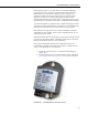
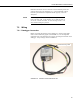

CS100 Barometric Pressure Sensor
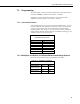
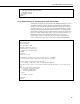
TABLE 7-1. Signal and Ground Connectors for CS100
Wire
CS100 Terminal
Datalogger
Single-Ended Measurement
Datalogger
Differential Measurement
Blue VOUT S.E. Input High Side of Diff Input
Yellow AGND
AG (CR10(X), CR500, CR510)
(Other Dataloggers)
Low Side of Diff. Input
Black GND
(21X, CR7, CR9000(X))
G (Other Dataloggers)
(21X, CR7, CR9000(X))
G (Other Dataloggers)
Green EXT TRIG
Control port (use to turn power
on/off)
Control port (use to turn power
on/off)
Red SUPPLY 12 VDC 12 VDC
Shield Shield
G (CR10(X), CR500, CR510)
(Other Dataloggers)
G (CR10(X), CR500, CR510)
(Other Dataloggers)
Improper wiring may damage the CS100 beyond repair.
WARNING
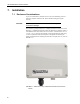
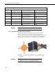
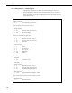
7.2.2 5-pin Screw Terminal Plug Connector
The datalogger connects to the CS100 via a 5-pin screw terminal plug
connector. This connector is removable and may be replaced. The
replacement connector may come with a connector key attached to it to ensure
that the connector is plugged into the CS100 right side up (see FIGURE 7-3).
When the connector is right side up, it will easily plug into the barometer.
FIGURE 7-3. Connector key attached to 5-pin screw terminal plug
connector
A 5-pin screw terminal that is plugged in upside down
will damage the sensor—perhaps beyond repair.
WARNING
10