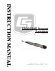
CS450/CS455 Pressure Transducer Revision: 1/13 C o p y r i g h t © 2 0 0 9 - 2 0 1 3 C a m p b e l l S c i e n t i f i c , I n c .
Warranty “PRODUCTS MANUFACTURED BY CAMPBELL SCIENTIFIC, INC. are warranted by Campbell Scientific, Inc. (“Campbell”) to be free from defects in materials and workmanship under normal use and service for twelve (12) months from date of shipment unless otherwise specified in the corresponding Campbell pricelist or product manual. Products not manufactured, but that are re-sold by Campbell, are warranted only to the limits extended by the original manufacturer.
Assistance Products may not be returned without prior authorization. The following contact information is for US and international customers residing in countries served by Campbell Scientific, Inc. directly. Affiliate companies handle repairs for customers within their territories. Please visit www.campbellsci.com to determine which Campbell Scientific company serves your country. To obtain a Returned Materials Authorization (RMA), contact CAMPBELL SCIENTIFIC, INC., phone (435) 227-9000.
Table of Contents PDF viewers: These page numbers refer to the printed version of this document. Use the PDF reader bookmarks tab for links to specific sections. 1. Introduction .................................................................1 1.1 Initial Inspection and Handling Guidelines..........................................1 2. Specifications .............................................................2 3. Configuration ..............................................................3 3.
Table of Contents 7. Maintenance ..............................................................19 7.1 7.2 Every Visit......................................................................................... 20 Every Two to Three Years or on a Rotating Schedule ...................... 20 8. Troubleshooting........................................................20 Appendix A. Calibration Certificate.............................................A-1 Figures 3-1. 3-2. 3-3. 3-4. 3-5. 3-6. 5-1. A-1.
CS450/CS455 Pressure Transducer The CS450/CS455 Submersible Pressure Transducer is designed for general pressure measurements. It uses the SDI-12 or RS-232 communications protocols to communicate with an SDI-12 or RS-232 recorder to simplify installation and programming. The CS450/CS455 can be used with an A150 desiccated case allowing the transducer to be connected to a CWS900 wireless sensor or prewired enclosure. 1.
CS450/CS455 Pressure Transducer Care should be taken when opening the package not to damage or cut the cable jacket. If there is any question about damage having been caused to the cable jacket, a thorough inspection is prudent. The model number and pressure range is etched on the housing. Check this information against the shipping documentation to ensure that the expected model number and range were received. Gauge pressure (Vented) devices must always have a desiccant tube attached.
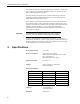
CS450/CS455 Pressure Transducer CAUTION Overpressure: 2x pressure range Dry Storage Temperature: -10° to 80°C Sensor will be damaged if it is encased in frozen liquid. Operating Temperature: 0° to 60°C Temperature Accuracy: ±0.2°C Maximum Cable Length: SDI-12 — one sensor connected to a single port can communicate up to approximately 457 m (1500 ft). With 10 sensors connected to a single port, each sensor can have up to 60 m (200 ft). RS-232 — 15 m (50 ft).
CS450/CS455 Pressure Transducer 3.1 Connection Communicating with the CS450/CS455 requires the sensor to be either connected to a PC or an SDI-12 Recorder. The sensor typically connects to a PC via the A200 sensor to PC interface. Many SDI-12 Recorders allow communication to the sensor via a terminal screen. Configurable settings can be changed via SDI-12 commands or by using Campbell Scientific’s software Device Configuration Utility. 3.1.
CS450/CS455 Pressure Transducer software package (e.g., LoggerNet) before and after the installation, or look in the Windows Device Manager list under the ports section (access via the control panel). FIGURE 3-1. A200 Sensor-to-PC Interface TABLE 3-2.
CS450/CS455 Pressure Transducer 3.1.2 Device Configuration Utility (version 1.12 or higher) The Device Configuration Utility (DevConfig) allows you to change the settings of the CS450/CS455. DevConfig is shipped on the CSI ResourceDVD included with the CS450/CS455. To use DevConfig, the transducer needs to be connected to the PC via the A200 (see Section 3.1.1, Using the A200). After installing DevConfig and connecting the transducer to the PC, select CS450 from the Device Type list (see FIGURE 3-2).
CS450/CS455 Pressure Transducer FIGURE 3-3. Connect screen There are three settings that can be changed: SDI-12 address, Pressure/Level Units, and Temperature Units. Double-click on the window of the units to be changed. This will open a Pick Menu box. Select the desired units and Apply the changes (see FIGURE 3-4). kPa FIGURE 3-4.
CS450/CS455 Pressure Transducer 3.1.3 SDI-12 Transparent Mode Transparent Mode allows direct communication with the CS450/CS455. This may require waiting for programmed datalogger commands to finish before sending responses. While in the transparent mode, datalogger programs may not execute. Datalogger security may need to be unlocked before transparent mode can be activated. Transparent mode is entered while the PC is in telecommunications with the datalogger through a terminal-emulator program.
CS450/CS455 Pressure Transducer CR10X-PB and CR510-PB dataloggers require “*#n” being entered at the prompt, where n is the control port being used. Now check for response from the sensor with address zero by typing the SDI12 Identify command “0I!” (that’s a zero, not the letter O). The sensor should respond with an identification string similar to “013CSI450.Std.01_xxxxxxxx”, where xxxxxxxx represents the eight-digit serial number.
CS450/CS455 Pressure Transducer FIGURE 3-6. HyperTerminal TABLE 3-4.
CS450/CS455 Pressure Transducer 3.2 SDI-12 Commands The CS450/CS455 uses an SDI-12-compatible hardware interface and supports a subset of the SDI-12 commands. The most commonly used command is the “aM!” command, issued by the datalogger. Here, a represents the sensor address. The communication sequence begins with the datalogger waking the sensor and issuing the aM! command. The transducer responds to the datalogger indicating that two measurements will be ready within two (2) seconds.
CS450/CS455 Pressure Transducer The CS450/CS455 is shipped from the factory with the address set to 0. The address on the CS450/CS455 can be changed by sending an SDI-12 change address command “aAb!”, where a is the original address and b is the new address. The change-address command can be issued from most SDI-12 recorders.
CS450/CS455 Pressure Transducer Only SDI-12 instructions aM!, aM7!, and aM8! output the results obtained when using the multiplier and offset. The offset and multiplier is only applied to the pressure/level value, not to the temperature. 3.2.2.2 Sample Number The extended SDI-12 command used to configure sample numbers is “aXCONFIG2=nnn!”, where nnn is the number of samples that will be measured to obtain the final output value, which is an average of the samples taken.
CS450/CS455 Pressure Transducer Pressure can be converted to feet of fresh water using the following simple equation: 1 psi = 2.31 feet of water For example, the maximum depth with a pressure range of 0 to 7.25 psig is 16.748 feet of water. 4.4 Well Installations Lower the transducer to an appropriate depth. CAUTION Do not drop the instrument or allow it to “free fall” down a well as this may damage the sensor. With long drops, it may be necessary to use the weighted nose cone (pn 25414).
CS450/CS455 Pressure Transducer For example, if the correct elevation of the water, as measured by a staff gauge or other measurement device, is 2015.50 feet, and the CS450 provides a reading of 5.76 psig, then: 5.76 psig * 2.31 ft/psig = 13.3056 ft. So, the offset is calculated: 2015.50 ft – 13.3056 ft = 2002.1944 ft This offset can be accounted for in the program instruction of the SDI-12 recorder. 5. Wiring 5.1 SDI-12 It is recommended to power down your system before wiring the CS450/CS455.
CS450/CS455 Pressure Transducer 5.2 RS-232 TABLE 5-2. RS-232 Wiring 5.
CS450/CS455 Pressure Transducer Keyboard/Display users and SCWIN users can jump ahead to the Maintenance section. 6.2 Using CRBasic or Edlog 6.2.1 CRBasic Programming Dataloggers that use CRBasic include our CR200-series, CR800, CR850, CR1000, CR3000, and CR5000. These dataloggers use the SDI12Recorder() to read the CS450/CS455. A multiplier of 1.0 and an offset of 0.0 yield water level in psig and temperature in degrees C.
CS450/CS455 Pressure Transducer Sample Program for CR1000 Datalogger ‘CR1000 Series Datalogger ‘Declare the variable for the water level measurement Public CS450(2) ‘Rename the variable names Alias CS450(1)=Level Alias CS450(2)=Temp_C ‘Define a data table for 60 minute maximum and minimums DataTable(Hourly,True,-1) DataInterval(0,60,Min,10) Maximum(1,Level,FP2,0,0) Minimum(1,Level,FP2,0,0) Maximum(1,Temp_C,FP2,0,0) Minimum(1,Temp_C,FP2,0,0) EndTable ‘Read sensor every 60 seconds BeginProg Scan(60,sec,1,0) ‘
CS450/CS455 Pressure Transducer 3. In the Start Address field, type in the number of the first input location. 4. In the Number of InLocs field, type in 2 and select OK. Below is a portion of a CR10X program that measures the CS450/CS455. NOTE The instructions below do not store data in final storage. Instruction 92, Instruction 77, and processing instructions such as Instruction 70 are required to store the data permanently.
CS450/CS455 Pressure Transducer Periodic evaluation of the desiccant is vital for keeping the vent tube dry. The CS450/CS455 ships with the desiccant tube attached. To assess the effectiveness of the desiccant, use one of the following: 7.1 7.2 • The desiccant in the tube changes color from blue to pink when the drying power is lost. • An enclosure humidity indicator such as CSI pn 28878 Humidity Indicator Card. Every Visit • Collect data. • Visually inspect wiring and physical conditions.
CS450/CS455 Pressure Transducer Problem: Transducer appears to be operating properly but data shows a periodic or cyclic fluctuation not attributable to water level changes. Suggestion: A kinked or plugged vent tube will not effectively vent a gauge pressure (Vented) type of device. Normal changes in barometric pressure will appear as water level fluctuations and these types of errors are typically on the order of 1 foot of water level.
CS450/CS455 Pressure Transducer 22
Appendix A. Calibration Certificate Each CS450/CS455 has been calibrated to meet printed accuracy specification at multiple temperature and pressure ranges. If additional verification is required, a Calibration Certificate can be purchased for each CS450/CS455 Submersible Pressure Transducer. This document included both the Certificate of Calibration and Instrument Data Report. A sample for illustration is provided (FIGURE A-1).
Appendix A.
Appendix A. Calibration Certificate bars = kPa / 100.0 psi = kPa * 0.145 FIGURE A-1.
Appendix A.
Campbell Scientific Companies Campbell Scientific, Inc. (CSI) 815 West 1800 North Logan, Utah 84321 UNITED STATES www.campbellsci.com • info@campbellsci.com Campbell Scientific Africa Pty. Ltd. (CSAf) PO Box 2450 Somerset West 7129 SOUTH AFRICA www.csafrica.co.za • cleroux@csafrica.co.za Campbell Scientific Australia Pty. Ltd. (CSA) PO Box 8108 Garbutt Post Shop QLD 4814 AUSTRALIA www.campbellsci.com.au • info@campbellsci.com.au Campbell Scientific do Brazil Ltda.