
User Manual


CS475, CS476, and CS477 Radar Water Level Sensor
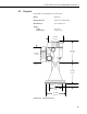
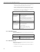
TABLE 7-1. Wiring Diagram
Color
Description
CR800,
CR850,
CR1000,
CR3000,
CR10(X),
CR510, CR500
CR23X
CR5000
CR200(X)
White SDI-12 Signal Odd Numbered
Control Port
(C1, C3…)
Odd Numbered
Control Port
(C1, C3…)
Odd Numbered
Control Port
(C1, C3…)
SDI-12 C1/SDI-12
Clear Chassis Ground
G
Red +12V (Power
Supply for
Sensor)
12V 12V 12V 12V Battery+
Black Ground G G
G G
7.4.2 Multiple Sensors Connection
To use more than one probe per datalogger, you can either connect the different
probes to different SDI-12 compatible ports on the datalogger or change the
SDI-12 addresses of the probes and let them share the same connection. Using
the SDI-12 address minimizes the use of ports on the datalogger and also
allows probes to be connected in a daisy-chain fashion which can minimize
cable runs in some applications.
7.4.3 Built-in Self Test (BIST)
After connecting the sensor to the datalogger’s power terminals, the sensor
performs a BIST (built-in self test) for approximately 80 seconds (factory
default). During this self-check, an internal check of the electronics occurs.
7.5 Programming
This section is for users who write their own datalogger
programs. A datalogger program to measure this sensor can be
created using Campbell Scientific’s Short Cut Program Builder
software. These sensors are not listed in the sensor list in Short
Cut. Instead, select SDI-12 sensor under General Measurements
(see Section 0, Step 4 — Use SCWin Short Cut to Program
Datalogger and Generate Wiring Diagram, for more information
about using Short Cut). You do not need to read this section to
use Short Cut.
NOTE
The radar sensor’s output is measured using a standard SDI-12 instruction to
read the data from an SDI-12 sensor. If using the sensor with other SDI-12
recorders, please refer to your system’s documentation. Further details of the
SDI-12 commands can be found in Appendix B and at: www.sdi-12.org.
17