
User Manual


CS475, CS476, and CS477 Radar Water Level Sensor
8. Diagnostics, Repair, and Maintenance
8.1 Testing Procedure
The test procedures for the sensor require the following steps:
1. Double check all wiring connections.
2. Connect the sensor to your datalogger and apply +12V power.
3. Compare the Output Stage versus the Actual Stage using the Start
Measurement command followed by the Send Data command (see Section
8.1.1, Start Measurement Command).
4. Send the Acknowledge Active command (see Section 8.1.2, Check Unit
Response). This command is used to check the presence of the sensor on
the bus. Only the address is sent back in response.
5. Send the Identification command (see Section 8.1.3, Check for Valid
Data).
6. Send the Start Verification command followed by the Get Data command
(see Section 8.1.4, Cyclic Redundancy Check).
7. Use the Get Unit command to ensure the units are what you want (see
Section 8.1.5, Get Units).
8. Use the Get Water Condition command to ensure that the water condition
fit the body of water you are monitoring (see Section 8.1.6, Get Water
Conditions).
9. Use the Get Power Operation Mode to ensure that the power mode is what
you want (see Section 8.1.7, Get Power Operation Mode).
10. Use the False Echo Learn command if you encounter a problem that could
be caused by noise (see Section 4.2, Step 2 — Do a False Echo Learn
Command).
8.1.1 Start Measurement Command
The 25616, Adjustment/Display Module, or the terminal emulator
in LoggerNet or PC400 can be used to enter this command.
Appendix B.2, Using Terminal Emulator and a Datalogger to
Send Commands, describes entering commands using the
terminal emulator. The Start Measurement command is also
used in CRBasic or Edlog programming. Refer to the Edlog help
for the appropriate command code entry.
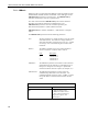
NOTE
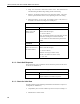
The aM! command requests measurement values from the sensor. This
command is always followed by the aD0! (Send Data) command (see TABLE
8-1). As a response of the Send Data command, the following information will
be returned.
21