
User Manual

Appendix A. Replacing the Cable
1
2
3
(A)
(C)
4
5
6
7
8
9
10
11
12
(D)
13
(B)
14
15
16
17
18
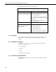
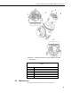
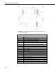
FIGURE A-1. Connecting the instrument housing (see TABLE A-1 for
description of labels)
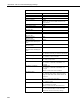
TABLE A-1. Description of Instrument Housing Labels
Connections Description
(A) Side Chamber SDI-12 Wiring
(B) Top Chamber Inner Housing Connections
(C) Typical SDI-12 Network Configuration
(D) DIS61 (Optional) (Reference V-2799S0)
1 Inner Housing Connections (Modular Plug Mounted in Dual
Chamber Housing), Plugs into Back of SDI-12 Board
2 SDI-12 Data
3 Ground Connection
4 Data Acquisition Device
5 Serial Data Line
6 12V (–) Ground
7 12V (+) Line
8 SDI-12 Sensor #1
9 SDI-12 Sensor #2
10 Ground Connection
11 To Instrument
12 Remote Display
13 Ground Connection
14 Digital Output (To Optional Remote Display)
15 Plug for Laptop Connection
16 Remote Display
17 Red
18 Other
A-2