CS511-L Dissolved Oxygen Probe Revision: 1/13 C o p y r i g h t © 2 0 0 1 - 2 0 1 3 C a m p b e l l S c i e n t i f i c , I n c .
Warranty “PRODUCTS MANUFACTURED BY CAMPBELL SCIENTIFIC, INC. are warranted by Campbell Scientific, Inc. (“Campbell”) to be free from defects in materials and workmanship under normal use and service for twelve (12) months from date of shipment unless otherwise specified in the corresponding Campbell pricelist or product manual. Products not manufactured, but that are re-sold by Campbell, are warranted only to the limits extended by the original manufacturer.
Assistance Products may not be returned without prior authorization. The following contact information is for US and international customers residing in countries served by Campbell Scientific, Inc. directly. Affiliate companies handle repairs for customers within their territories. Please visit www.campbellsci.com to determine which Campbell Scientific company serves your country. To obtain a Returned Materials Authorization (RMA), contact CAMPBELL SCIENTIFIC, INC., phone (435) 227-9000.
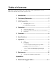
Table of Contents PDF viewers: These page numbers refer to the printed version of this document. Use the PDF reader bookmarks tab for links to specific sections. 1. Introduction .................................................................1 2. Cautionary Statements...............................................2 3. Initial Inspection .........................................................2 3.1 Shipping Kit and Accessories ..............................................................2 3.1.
Table of Contents B. Sensorex’s Model DO6200/T ..................................B-1 B.1 B.2 DO6200/T Specifications ................................................................ B-1 Accessories for DO6200/T .............................................................. B-2 C. PT4-L Agitator .........................................................C-1 C.1 C.2 C.3 Description ...................................................................................... C-1 PT4-L Specifications ...............
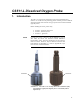
CS511-L Dissolved Oxygen Probe 1. Introduction The CS511 is a rugged, low-maintenance sensor that is manufactured by Sensorex. It consists of a self-polarizing galvanic cell that generates a millivolt signal proportional to the amount of oxygen present in the measured medium (typically water). Before installing the CS511, please study • • • NOTE DO6400/T Section 2, Cautionary Statements Section 3, Initial Inspection Section 3.1, Quickstart Currently, the CS511 is Sensorex’s Model DO6400/T.
CS511-L Dissolved Oxygen Probe 2. 3. Cautionary Statements • The CS511 is a precision instrument. Please handle it with care. • Because the CS511 is shipped dry, electrolyte needs to be added before using the probe (see Section 4.1, Getting Probe Ready to Use). • Letting the CS511 dry up shortens the life of the membrane and probe. • Drain the solution from the CS511 before storing it out of water.
CS511-L Dissolved Oxygen Probe 4. Quickstart Please review Section 7, Operation, for wiring, programming, and calibration information. 4.1 Getting Probe Ready to Use 1. Unscrew the lower body from the upper body. 2. Inspect the membrane for wrinkles. Replace membrane if wrinkled (see Section 8.1, Cleaning Probe and Replacing the Membrane).
CS511-L Dissolved Oxygen Probe 3. Pour clean water into the lower body and look for leakage around the membrane. Dispose of the water, and if there is leakage, replace membrane (see Section 8.1, Cleaning Probe and Replacing the Membrane). 4. Pour fresh electrolyte in the bottom cap and fill to the top of the cap. 5. Keep the probe upright with the cable pointed upwards (not sideways). Screw the bottom cap onto the upper body until hand tight.
CS511-L Dissolved Oxygen Probe 4.2 Use SCWin to Program Datalogger and Generate Wiring Diagram The simplest method for programming the datalogger to measure the 034B is to use Campbell Scientific’s SCWin Program Generator. 1. Open Short Cut and click on New Program. 2. Select the datalogger and enter the scan interval.
CS511-L Dissolved Oxygen Probe 6 3. Select CS511 Dissolved Oxygen Probe, and select the right arrow (in center of screen) to add it to the list of sensors to be measured, and then select Next. 4. Define the name of the public variables and enter the calibration multiplier. Variables default to DOmv for the millivolt measurements and DOppm for the ppm values. The default calibration value of 0.34 is based on an average. It is preferable to calibrate the probe using the procedure provided in Section 7.
CS511-L Dissolved Oxygen Probe NOTE 5. Choose the outputs and then select Finish. 6. In the Save As window, enter an appropriate file name and select Save. 7. In the Confirm window, click Yes to download the program to the datalogger. 8. Click on Wiring Diagram and wire according to the wiring diagram generated by SCWin Short Cut. Campbell Scientific also recommends connecting the shield wire to ground.
CS511-L Dissolved Oxygen Probe 4.3 Mount Probe Mount the CS511 in water at a slight angle, which prevents bubbles from becoming trapped on the membrane. 5. Overview The CS511 is a galvanic probe which produces a millivolt signal proportional to the amount of oxygen present in the measured medium. Oxygen diffuses through the membrane onto the cathode, reacts chemically, and combines with the anode.
CS511-L Dissolved Oxygen Probe membrane in a screw-on membrane cap. Regular servicing is not required. When necessary, the probe can be fully overhauled in five min. The CS511’s cable can terminate in: • • • 6. Pigtails that connect directly to a Campbell Scientific datalogger (option –PT). Connector that attaches to a prewired enclosure (option –PW). Refer to www.campbellsci.com/prewired-enclosures for more information. Connector that attaches to a CWS900 Wireless Sensor Interface (option –CWS).
CS511-L Dissolved Oxygen Probe Shipping Weight 0.8 kg (1.75 lb) Cable Jacket Material: PVC Operating Conditions: Temperature Pressure: Minimum Submersion Depth: Minimum Water Flow: 0° to 50°C (32° to 122°F) 0 to 100 psig 60 mm (2.5 in) 5 cm/s (2 in/sec) across membrane Calibration: In air or in air saturated water Temperature Compensation: Automatic from 4° to 40°C (40° to 104°F) Range of Dissolved Oxygen: 0.
CS511-L Dissolved Oxygen Probe 7. Operation 7.1 Wiring The CS511 can use one differential channel or one single-ended channel. Differential wiring is better at rejecting electrical noise and ground loop error. TABLE 7-1. Sensor Wiring 7.
CS511-L Dissolved Oxygen Probe 7.2.1.1 Example CR1000 Program Using VoltDiff This example is a CR1000 program but programming for the CR800, CR850, CR3000, and CR5000 is similar. TABLE 7-2 shows the wiring for the example. TABLE 7-2.
CS511-L Dissolved Oxygen Probe 7.2.1.2 Example CR200(X) Program The CR200(X)-series must use the VoltSE() instruction since these dataloggers do not make differential measurements. If the other CRBasic dataloggers use the VoltSE() instruction instead of the VoltDiff() instruction, their programming will be similar to this example. TABLE 7-3 shows the wiring for the example. TABLE 7-3.
CS511-L Dissolved Oxygen Probe 7.2.2 Edlog In Edlog, P1 is used for single-ended measurements, and P2 is used for differential measurements. Section 7.2.2.1, Portion of CR10X Sample Program Using P1, and Section 7.2.2.2, Portion of CR10X Sample Program Using P2, provide examples. 7.2.2.1 Portion of CR10X Sample Program Using P1 NOTE 1: Volt (SE) (P1) 1: 1 2: 24 3: 1 4: 1 5: 1.0 6: 0.0 The example measurement instructions that follow do not store data to final storage.
CS511-L Dissolved Oxygen Probe 4) Place the CS511 in air away from direct sunlight with the membrane facing upward. 5) Place a drop of clean water on the membrane. 6) Wait for readings to stabilize. This may take 15 minutes or more. 7) Determine the air temperature and barometric pressure. 8) Using a calibration chart such as that provided in Appendix A, determine the oxygen concentration of the air.
CS511-L Dissolved Oxygen Probe 8. Maintenance The only maintenance required is regular cleaning and replacement of the membrane (see below). 8.1 Cleaning Probe and Replacing the Membrane 1. Unscrew the lower body from the upper body (FIGURE 8-1). FIGURE 8-1. Separate the lower body from the upper body 2. 16 Safely dispose of the electrolyte. Make sure the cap’s O-ring does not fall out of the cap.
CS511-L Dissolved Oxygen Probe 3. Using the membrane tool, unscrew the membrane lock that is in the lower body (see FIGURE 8-2). 4. Remove and dispose of the membrane and its O-ring as show in FIGURE 8-2. Membrane Tool Membrane Lock Spacer Membrane Membrane O-ring Cap O-ring FIGURE 8-2.
CS511-L Dissolved Oxygen Probe 5. To clean, immerse the top part of the sensor in distilled white vinegar (3% acetic acid) for about 30 min. If vinegar is unavailable, use a soft toothbrush, automatic dishwasher detergent, and clean water to clean the cathode, anode, and plastic. Rinse all components thoroughly with clean water after cleaning (see FIGURE 8-3). FIGURE 8-3.
CS511-L Dissolved Oxygen Probe 6. Replace the membrane and its O-ring by first placing the new O-ring at the very bottom of the membrane cavity (see FIGURE 8-4). Remove the paper backing from a new membrane and place the new membrane on top of the O-ring, and then place the spacer on top of the membrane. Using the membrane tool, install the membrane lock on top of the spacer as shown in FIGURE 8-5. Make sure the cap is upright (not sideways) when securing the membrane lock to the spacer. FIGURE 8-4.
CS511-L Dissolved Oxygen Probe Membrane Tool Membrane Lock Spacer Membrane O-ring FIGURE 8-5. Installing membrane 7. 20 Inspect the membrane for wrinkles; replace membrane if wrinkled.
CS511-L Dissolved Oxygen Probe 8. Pour some clean water into the lower body and look for leakage around the membrane (see FIGURE 8-6); replace membrane if there is leakage. If there is no leakage, dispose of the water. r W a te FIGURE 8-6. Check for leakage 9. Pour fresh electrolyte in the bottom cap and fill to the top of the cap. 10. Keep the sensor upright so that the cable is pointed upwards (not sideways). Screw the bottom cap onto the upper body until hand tight.
CS511-L Dissolved Oxygen Probe 22
Appendix A.
Appendix A.
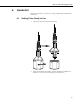
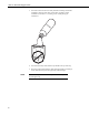
Appendix B. Sensorex’s Model DO6200/T Prior to June 2008, Campbell Scientific’s CS511 was Sensorex’s model DO6200/T (see FIGURE B-1) instead of Sensorex’s model DO6400/T. Programming, wiring, and some specifications are the same for these two sensors. However, they look different and use different accessories. FIGURE B-1. Sensorex’s model DO6200/T B.1 DO6200/T Specifications Principle of Measurement: Membrane covered, galvanic oxygen probe Output Signal: 1.65 mV ± 0.
Appendix B. Sensorex’s Model DO6200/T Dimensions and Weight: 8.9 cm (3.5 in) height, 5.6 cm (2.2 in) diameter, 0.5 kg (1.1 lb) Cable Length: 3 m (10 ft) Cable Description: 5-wire, 22 AWG-shielded, PVC jacketed Operating Conditions: Temperature Pressure: Minimum Submersion Depth: Minimum Water Flow: 0° to 50°C (32° to 122°F) Maximum 10 atmospheres (147 psig) 60 mm (2.
Appendix C. PT4-L Agitator C.1 Description The PT4 agitator is a reliable, robust agitator for use in conjunction with probes subjected to bio-fouling in ponds and stagnant water conditions (flow <5 cm/s). O2 probes require a minimum water velocity across their membranes to function properly. Therefore, to measure DO in stagnant water conditions, it is necessary to move the water past the membrane to get accurate and reliable DO measurements.
Appendix C. PT4-L Agitator FIGURE C-2. DO sensor with PT4 Agitator C.2 PT4-L Specifications Diameter: 8.3 cm (3.25 in) Length: 18.0 cm (7.125 in) Weight: 0.6 kg (1.25 lb) Cable length: 3 m (10 ft) Power requirements: 10.5 to 18 Vdc at the agitator Active current consumption: 1.1 A Maximum ON time: 3s C.3 Agitator Control Campbell Scientific ships the agitator with a repeat cycle timer. Using the repeat-cycle timer requires no datalogger programming.
Appendix C. PT4-L Agitator The wiring for the agitator as controlled by this example program is as follows: Gro und/G 4 Datalogger Port C1 WHITE 1 Agitator #7321 Relay Crydo m D1D07 3 2 BLUE + 12 V Battery FIGURE C-3. Agitator Wiring The following instructions would trigger the agitator as discussed in the agitator manual.
Appendix C. PT4-L Agitator The CR510, CR10X, and CR23X use instruction P86 and P22 as follows: CR10X P86 and P22 Instructions Example 45: Do (P86) 1: 41 Set Port 1 High 46: Excitation with Delay (P22) 1: 1 Ex Channel 2: 20 Delay W/Ex (units = 0.01 sec) 3: 0 Delay After Ex (units = 0.01 sec) 4: 0 mV Excitation 47: Do (P86) 1: 51 Set Port 1 Low 48: End (P95) The above examples are not as power efficient as possible and would require AC power to maintain a sufficient battery charge.
Campbell Scientific Companies Campbell Scientific, Inc. (CSI) 815 West 1800 North Logan, Utah 84321 UNITED STATES www.campbellsci.com • info@campbellsci.com Campbell Scientific Africa Pty. Ltd. (CSAf) PO Box 2450 Somerset West 7129 SOUTH AFRICA www.csafrica.co.za • cleroux@csafrica.co.za Campbell Scientific Australia Pty. Ltd. (CSA) PO Box 8108 Garbutt Post Shop QLD 4814 AUSTRALIA www.campbellsci.com.au • info@campbellsci.com.au Campbell Scientific do Brazil Ltda.