INSTRUCTION MANUAL CS547 Conductivity and Temperature Probe and A547 Interface Revision: 9/00 C o p y r i g h t ( c ) 1 9 9 4 - 2 0 0 0 C a m p b e l l S c i e n t i f i c , I n c .
Warranty and Assistance The CS547 CONDUCTIVITY AND TEMPERATURE PROBE AND A547 INTERFACE are warranted by CAMPBELL SCIENTIFIC, INC. to be free from defects in materials and workmanship under normal use and service for twelve (12) months from date of shipment unless specified otherwise. Batteries have no warranty. CAMPBELL SCIENTIFIC, INC.'s obligation under this warranty is limited to repairing or replacing (at CAMPBELL SCIENTIFIC, INC.'s option) defective products.
CS547 Probe and A547 Interface Table of Contents PDF viewers note: These page numbers refer to the printed version of this document. Use the Adobe Acrobat® bookmarks tab for links to specific sections. 1. Overview......................................................................1 1.1 EC Sensor .................................................................................................1 1.2 A547 Interface ..........................................................................................
CS547 Probe and A547 Interface Table of Contents 9. Deriving a Temperature Compensation Coefficient ..............................................................15 10. Instruction 11 Details..............................................15 11. Electrically Noisy Environments............................16 12. Long Lead Lengths Temperature...........................17 13. CS547 Schematic ....................................................
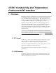
CS547 Conductivity and Temperature Probe and A547 Interface 1. Overview The CS547 conductivity and temperature probe, and A547 interface are designed for measuring the electrical conductivity, dissolved solids, and temperature of fresh water with Campbell Scientific dataloggers. They require the use of AC excitation, so they can be used with the CR10(X), 21X, and CR7 dataloggers but not with the BDR301 or BDR320. Use with multiplexers is possible.
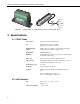
ND CO EX TE M P SOR EX LD IE SH CO ND SEN TE M P ND R SH IE LD CO HI LO M GGE CO ND CO ND TE DATA LO EX AG SE EX TE M P P CS547 Conductivity and Temperature Probe and A547 Interface A54 Log an, 7 IN Uta TER h FAC E MA DE IN US A A547 FIGURE 1-1. A547 Interface and CS547 Conductivity and Temperature Probe 2. Specifications 2.1 CS547 Probe Construction The probe housing is stainless steel Size Probe Length: 3.7 inches (94 mm) Diameter: 0.95 inches (24.
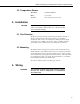
CS547 Conductivity and Temperature Probe and A547 Interface 2.3 Temperature Sensor Thermistor Betatherm 100K6A1. Range 0°C to 50°C. Accuracy Error ±0.4°C (See Section 8.2). 3. Installation CAUTION Rapid heating and cooling of the probe, such as leaving it in the sun and then submersing it in a cold stream, may cause irreparable damage. 3.
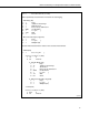
CS547 Conductivity and Temperature Probe and A547 Interface AG SE TEMP SE3 EX TEMP EX2 EX COND HI COND DATALOGGER AG EX1 1H 1L LO COND SHIELD SHIELD Red (Temp) TEMP Orange (Cond) COND Black (Ex Cond) EX COND Green (Ex Temp) EX TEMP SENSOR Clear (Shield) FIGURE 4-1. CS547 Wiring Diagram for Example Below 5. Programming 5.1 Programming Overview Typical datalogger programs to measure the CS547 consist of four parts: 1. Measurement of EC and temperature 2.
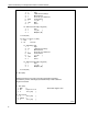
CS547 Conductivity and Temperature Probe and A547 Interface *Table 1 Program 01: 5 Execution Interval (seconds) ;Make a preliminary measurement of resistance for autoranging. 1: Full Bridge (P6) 1: 1 Reps 2: 15 ±2500 mV Fast Range 3: 1 DIFF Channel 4: 1 Excite all reps w/Exchan 1 5: 2500 mV Excitation 6: 1 Loc [ Rs ] 7: -.001 Mult 8: 1 Offset 2: BR Transform Rf [X/(1-X)] (P59) 1: 1 Reps 2: 1 Loc [ Rs ] 3: 1 Multiplier (Rf) ; ;Test the initial measurement to make a more accurate measurement.
CS547 Conductivity and Temperature Probe and A547 Interface 9: Full Bridge (P6) 1: 1 Reps 2: 15 ±2500 mV Fast Range 3: 1 DIFF Channel 4: 1 Excite all reps w/Exchan 1 5: 2500 mV Excitation 6: 1 Loc [ Rs ] 7: -.
CS547 Conductivity and Temperature Probe and A547 Interface 19: Z=X*F (P37) 1: 5 X Loc [ Rp 2: -.1 F 3: 5 Z Loc [ Rp 20: Z=X+F (P34) 1: 5 X Loc [ Rp 2: -.005 F 3: 5 Z Loc [ Rp ] ] ] ] 21: Z=X+Y (P33) 1: 1 X Loc [ Rs ] 2: 5 Y Loc [ Rp ] 3: 1 Z Loc [ Rs ] ; ;EC is then calculated by multiplying the reciprocal of resistance, ;which is conductance, by the cell constant. ; NOTE: The cell constant (Kc) is printed on the label of each sensor or it can be calculated (see Section 6.4).
CS547 Conductivity and Temperature Probe and A547 Interface The following program segment automatically chooses which correction to apply to the measurement. ; ;The following program set corrects for errors of ionization in the EC ;measurement. ; 25: IF (X<=>F) (P89) 1: 3 X Loc [ Ct 2: 4 < 3: .474 F 4: 30 Then Do ] 26: Z=X*F (P37) 1: 3 X Loc [ Ct 2: .95031 F 3: 3 Z Loc [ Ct 27: Z=X+F (P34) 1: 3 X Loc [ Ct 2: -.
CS547 Conductivity and Temperature Probe and A547 Interface ;This next program set will correct errors in the EC measurement resulting ;from temperature differences. ; 31: Z=X+F (P34) 1: 4 X Loc [ Temp_degC ] 2: -25 F 3: 6 Z Loc [ A ] 32: Z=X*F (P37) 1: 3 X Loc [ Ct ] 2: 100 F 3: 7 Z Loc [ lOO_Ct ] 33: Z=X*F (P37) 1: 6 X Loc [ A ] 2: nnn F 3: 8 Z Loc [ TC_Proces ] Enter TC (%/°C) to correct cond. reading.
CS547 Conductivity and Temperature Probe and A547 Interface *Table 2 Program 02: 0.0 Execution Interval (seconds) *Table 3 Subroutines End Program (End) 6. Calibration 6.1 Conversion Factors 1 S (Siemens) = 1 mho = 1/ohm Although mS·cm-1 and µS·cm-1 are the commonly used units of EC, the SI base unit is S·m-1. The result of the example programs is mS·cm-1 EC measurements can be used to estimate dissolved solids. For high accuracy, calibration to the specific stream is required.
CS547 Conductivity and Temperature Probe and A547 Interface 3. Connect the CS547 and A547 or probe and interface to the datalogger using the wiring described in Section 4. Enter the following program into the datalogger. The calibration solution temperature must be between 1°C and 35°C; the polynomial in step 11 (P58) corrects for temperature errors within this range. The solution constant of 1.408 mS cm-1 (for prepared solution mentioned above), entered in step 13 (P37), is valid only for a 0.
CS547 Conductivity and Temperature Probe and A547 Interface 09: Z=X+F (P34) 01: 2 02: -25 03: 3 X Loc t F Z Loc [(t-25).01] 10: Z=X*F (P37) 01: 3 02: .01 03: 3 X Loc (t-25).01 F Z Loc [(t-25).01] 11: Polynomial (P55) 01: 1 02: 3 03: 4 04: .99124 05: -1.8817 06: 3.4789 07: -3.51 08: -1.2 09: -43 Rep X Loc (t-25).01 F(X) Loc [f(t) ] C0 C1 C2 C3 C4 C5 12: Z=1/X (P42) 01: 4 02: 6 X Loc f(t) Z Loc [1/f(t) 13: Z=X*F (P37) 01: 6 02: 1.
CS547 Conductivity and Temperature Probe and A547 Interface Correction of Ionization Errors: Figures 8.1-1 and 8.1-2 show the amount of correction applied by the example program to compensate for ionization effects on the measurements. Also shown is an ideal correction. Factors were derived by measuring the standard solutions described in Section 2.2 with values of 0.0234, 0.07, 0.4471, 07, 1.413, 2.070, 3.920, and 7.0 mS cm-1. FIGURE 8.1-1. Plot of Ideal and Actual Correction between 0 and 0.
CS547 Conductivity and Temperature Probe and A547 Interface 8.2 Temperature Measurement Error The overall probe accuracy is a combination of the thermistor's interchangeability specification, the precision of the bridge resistors, and the polynomial error. In a "worst case" all errors add to an accuracy of ±0.4°C over the range of -24° to 48°C and ±0.9°C over the range of -38°C to 53°C. The major error component is the interchangeability specification of the thermistor, tabulated in Table 8.2-1.
CS547 Conductivity and Temperature Probe and A547 Interface 9. Deriving a Temperature Compensation Coefficient 1. Place the CS547 in a sample of the solution to be measured. Bring the sample and the probe to 25°C. 2. Enter the example program from Section 5.2 in the datalogger and record Ct at 25°C from Location 3. This number will be C25 in the formula in Step 4. 3. Bring the solution and the probe to a temperature (t) near the temperature at which field measurements will be made.
CS547 Conductivity and Temperature Probe and A547 Interface TABLE 10-1. Temperature , Resistance, and Datalogger Output 0.00 2.00 4.00 6.00 8.00 10.00 12.00 14.00 16.00 18.00 20.00 22.00 24.00 26.00 28.00 30.00 32.00 34.00 36.00 38.00 40.00 42.00 44.00 46.00 48.00 50.00 52.00 54.00 56.00 58.00 60.00 351017 315288 283558 255337 230210 207807 187803 169924 153923 139588 126729 115179 104796 95449 87026 79428 72567 66365 60752 55668 51058 46873 43071 39613 36465 33598 30983 28595 26413 24419 22593 -0.06 1.
CS547 Conductivity and Temperature Probe and A547 Interface Example 2. Sample CR10(X) Instructions Using AC Half Bridge 01: AC Half Bridge (P5) 01: 1 Rep 02: 22** 7.5 mV 60 Hz rejection Range 03: 9* IN Chan 04: 3* Excite all reps w/EXchan 3 05: 2000** mV Excitation 06: 11* Loc [:Air_Temp ] 07: 800 Mult 08: 0 Offset 02: Polynomial (P55) 01: 1 02: 11* 03: 11* 04: -53.46 05: 90.807 06: -83.257 07: 52.283 08: -16.723 09: 2.
CS547 Conductivity and Temperature Probe and A547 Interface 02: Polynomial (P55) 01: 1 02: 11* 03: 11* 04: -53.46 05: 90.807 06: -83.257 07: 52.283 08: -16.723 09: 2.211 Rep X Loc Temp_C F(X) Loc [:Temp_C ] C0 C1 C2 C3 C4 C5 * Proper entries will vary with program and datalogger channel and input location assignments. ** On the 21X and CR7 use the 15 mV input range and 4000 mV excitation. *** Use a multiplier of 0.2 with a 21X and CR7. 13.
CS547 Conductivity and Temperature Probe and A547 Interface Datalogger Connections EX COND HI COND LO COND AG Sensor Connections 1K R2 220µFD + 220µFD + 1K 220µFD + 220µFD + EX TEMP EX COND COND R1 SE TEMP TEMP EX TEMP SHIELD SHIELD FIGURE 13-2.
CS547 Conductivity and Temperature Probe and A547 Interface This is a blank page.
This is a blank page.
Campbell Scientific Companies Campbell Scientific, Inc. (CSI) 815 West 1800 North Logan, Utah 84321 UNITED STATES www.campbellsci.com info@campbellsci.com Campbell Scientific Africa Pty. Ltd. (CSAf) PO Box 2450 Somerset West 7129 SOUTH AFRICA www.csafrica.co.za sales@csafrica.co.za Campbell Scientific Australia Pty. Ltd. (CSA) PO Box 444 Thuringowa Central QLD 4812 AUSTRALIA www.campbellsci.com.au info@campbellsci.com.au Campbell Scientific do Brazil Ltda.