CS547A Conductivity and Temperature Probe and A547 Interface Revision: 10/11 C o p y r i g h t © 1 9 9 4 - 2 0 1 1 C a m p b e l l S c i e n t i f i c , I n c .
Warranty “PRODUCTS MANUFACTURED BY CAMPBELL SCIENTIFIC, INC. are warranted by Campbell Scientific, Inc. (“Campbell”) to be free from defects in materials and workmanship under normal use and service for twelve (12) months from date of shipment unless otherwise specified on the corresponding Campbell invoice. Batteries, fine-wire thermocouples, desiccant, and other consumables have no warranty.
Assistance Products may not be returned without prior authorization. The following contact information is for US and international customers residing in countries served by Campbell Scientific, Inc. directly. Affiliate companies handle repairs for customers within their territories. Please visit www.campbellsci.com to determine which Campbell Scientific company serves your country. To obtain a Returned Materials Authorization (RMA), contact CAMPBELL SCIENTIFIC, INC., phone (435) 227-2342.
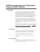
CS547A Probe and A547 Interface Table of Contents PDF viewers: These page numbers refer to the printed version of this document. Use the PDF reader bookmarks tab for links to specific sections. 1. Overview.......................................................................1 1.1 EC Sensor .................................................................................................1 1.2 A547 Interface ..........................................................................................1 2.
CS547A Probe and A547 Interface Table of Contents 10. Therm107 / P11 Instruction Details ........................18 11. Electrically Noisy Environments ............................20 12. Long Lead Lengths Temperature ...........................20 13. CS547A Schematic ..................................................21 Figures 1-1. A547 Interface and CS547A Conductivity and Temperature Probe ...... 2 4-1. CS547A wiring diagram for example below .......................................... 4 8.1-1.
CS547A Conductivity and Temperature Probe and A547 Interface 1. Overview The CS547A conductivity and temperature probe, and A547 interface are designed for measuring the electrical conductivity, dissolved solids, and temperature of fresh water with Campbell Scientific dataloggers. This sensor can be used with any CSI logger that can issue a negative excitation. This includes most new CRBasic dataloggers as well as older, Edlog loggers.
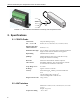
CS547A Conductivity and Temperature Probe and A547 Interface FIGURE 1-1. A547 Interface and CS547A Conductivity and Temperature Probe 2. Specifications 2.1 CS547A Probe Construction The probe housing is epoxy Size — L x W x H 89 mm (3.5 in.) x 25.4 mm (1 in.) x 19 mm (0.75 in.) Minimum Pipe ID in which CS547A Fits 28 mm (1.1 in.) Maximum Cable Length 305 m (1000 ft). The sensor must be ordered with desired length as cable cannot be added to existing probes.
CS547A Conductivity and Temperature Probe and A547 Interface 2.3 Temperature Sensor Thermistor Betatherm 100K6A1. Range 0° to 50°C. Accuracy Error ±0.4°C (See Section 8.2). 3. Installation CAUTION Rapid heating and cooling of the probe, such as leaving it in the sun and then submersing it in a cold stream, may cause irreparable damage. 3.
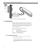
CS547A Conductivity and Temperature Probe and A547 Interface Datalogger or AG A547 AG SE TEMP VX2 or EX2 EX TEMP VX1 or EX1 EX COND 1H HI COND 1L LO COND Ground DATALOGGER SE3 SHIELD SHIELD Clear (Shield) TEMP Red (Temp) SENSOR COND Orange (Cond) Black (Ex Cond) EX COND Green (Ex Temp) EX TEMP FIGURE 4-1. CS547A wiring diagram for example below 5. Programming All example programs may require modification by the user to fit the specific application's wiring and programming needs.
CS547A Conductivity and Temperature Probe and A547 Interface 2. Correction of ionization errors in EC measurements Ionization caused by the excitation of the EC sensor can cause large errors. Campbell Scientific has developed a linear correction for conductivity between 0.005 and 0.44 mS cm-1, and a quadratic correction for conductivity between 0.44 and 7.0 mS cm-1. Corrections were determined in standard salt solutions containing KCl, Na2SO4, NaHCO3, and NaCl. 3.
CS547A Conductivity and Temperature Probe and A547 Interface '\\\\\\\\\\\\\\\\\\\\\\\\\\\ PROGRAM //////////////////////////// BeginProg 'evaluate and edit each of these 3 user specific values Rcable=25 'edit this value to the actual footage of cable on your sensor CellConstant=1.
CS547A Conductivity and Temperature Probe and A547 Interface 'correct errors in the EC measurement due to temperature Therm107 (TempDeg_C,1,3,Vx2,0,250,1,0) C25mScm = (Ct * 100)/(((TempDeg_C-25) * TempCoef) + 100) 'end scan loop by calling output table CallTable ECSample NextScan EndProg 5.2.2 Edlog *Table 1 Program 01: 5 Execution Interval (seconds) ;Make a preliminary measurement of resistance for autoranging.
CS547A Conductivity and Temperature Probe and A547 Interface 6: BR Transform Rf[X/(1-X)] (P59) 1: 1 Reps 2: 1 Loc [ Rs ] 3: 1 Multiplier (Rf) 7: End (P95) 8: If Case Location < F (P83) 1: 9.25 F 2: 30 Then Do 9: Full Bridge (P6) 1: 1 Reps 2: 15 ±2500 mV Fast Range 3: 1 DIFF Channel 4: 1 Excite all reps w/Exchan 1 5: 2500 mV Excitation 6: 1 Loc [ Rs ] 7: -.
CS547A Conductivity and Temperature Probe and A547 Interface ; ;Subtract resistance errors (Rp) caused by the blocking capacitors ;(0.005Kohm) and the cable length (0.000032kohm/ft). Enter cable lead ;length in nnn below. ; 17: Z=F (P30) 1: nnn 2: 00 3: 5 F Exponent of 10 Z Loc [ Rp ] 18: Z=X*F (P37) 1: 5 X Loc [ Rp 2: .00032 F 3: 5 Z Loc [ Rp 19: Z=X*F (P37) 1: 5 X Loc [ Rp 2: -.1 F 3: 5 Z Loc [ Rp Enter cable length in feet. ] ] ] ] 20: Z=X+F (P34) 1: 5 X Loc [ Rp 2: -.
CS547A Conductivity and Temperature Probe and A547 Interface 24: IF (X<=>F) (P89) 1: 3 X Loc [ Ct 2: 4 < 3: .474 F 4: 30 Then Do ] 25: Z=X*F (P37) 1: 3 X Loc [ Ct 2: .95031 F 3: 3 Z Loc [ Ct 26: Z=X+F (P34) 1: 3 X Loc [ Ct 2: -.00378 F 3: 3 Z Loc [ Ct ] ] ] ] 27: Else (P94) 28: Polynomial (P55) 1: 1 Reps 2: 3 X Loc [ Ct ] 3: 3 F(X) Loc [ Ct ] 4: -.02889 C0 5: .98614 C1 6: .02846 C2 7: .000000 C3 8: .000000 C4 9: .
CS547A Conductivity and Temperature Probe and A547 Interface 33: Z=X*F (P37) 1: 6 X Loc [ A 2: nnn F 3: 8Z Loc [ TC_Proces ] ] Enter TC (%/°C) to correct cond. reading. 34: Z=X+F (P34) 1: 8 X Loc [ TC_Proces ] 2: 100 F 3: 8 Z Loc [ TC_Proces ] 35: Z=X/Y (P38) 1: 7 X Loc [ Ct100 ] 2: 8 Y Loc [ TC_Proces ] 3: 9 Z Loc [ C25mScm_l ] EC corrected for temperature. ;Output processing, convention states that the temperature be reported ;with the EC measurement.
CS547A Conductivity and Temperature Probe and A547 Interface 6. Calibration 6.1 Conversion Factors 1 S (Siemens) = 1 mho = 1/ohm Although mS·cm-1 and µS·cm-1 are the commonly used units of EC, the SI base unit is S·m-1. The result of the example programs is mS·cm-1 EC measurements can be used to estimate dissolved solids. For high accuracy, calibration to the specific stream is required.
CS547A Conductivity and Temperature Probe and A547 Interface The calibration solution temperature must be between 1°C and 35°C; a polynomial is used to correct for temperature errors within this range. The solution constant of 1.408 mS cm-1 (for prepared solution mentioned above), is valid only for a 0.01 molal KCl solution. 6.4.
CS547A Conductivity and Temperature Probe and A547 Interface 2: BR Transform Rf[X/(1-X)] (P59) 1: 1 Rep 2: 1 Loc [Rs ] 3: 1 Multiplier (Rf) 3: Z=F (P30) 1: nnn 2: 00 3: 5 F Exponent of 10 Loc [Rp ] 4: Z=X*F (P37) 1: 5 2: .00032 3: 5 Loc [Rp F Loc [Rp ] 5: Z=X*F (P37) 1: 5 2: -.1 3: 5 Loc [Rp F Loc [Rp ] ] ] 6: Z=X+F (P34) 1: 5 2: -.
CS547A Conductivity and Temperature Probe and A547 Interface 11: Polynomial (P55) 1: 1 Rep 2: 3 X Loc [T25_01] 3: 4 F(X) Loc [f_of_T 4: .99124 C0 5: -1.8817 C1 6: 3.4789 C2 7: -3.51 C3 8: -1.2 C4 9: -43 C5 12: Z=1/X (P42) 1: 4 2: 6 ] X Loc [f_of_T ] Z Loc [one_ovrfT ] 13: Z=X*F (P37) 1: 6 X Loc [one_ovrfT 2: 1.408 F 3: 7 Z Loc [Conductiv] ] EC of calibration solution 14: Z=X*Y (P36) 1: 7 X Loc [Conductiv] 2: 1 Y Loc [Rs ] 3: 8 Z Loc [Kc ] End 7.
CS547A Conductivity and Temperature Probe and A547 Interface derived by measuring the standard solutions described in Section 2.2 with values of 0.0234, 0.07, 0.4471, 07, 1.413, 2.070, 3.920, and 7.0 mS cm-1. FIGURE 8.1-1. Plot of ideal and actual correction between 0 and 0.44 mS cm-1 FIGURE 8.1-2. Plot of ideal and actual correction between 0.44 and 7.
CS547A Conductivity and Temperature Probe and A547 Interface 8.2 Temperature Measurement Error The overall probe accuracy is a combination of the thermistor's interchangeability specification, the precision of the bridge resistors, and the polynomial error. In a "worst case" all errors add to an accuracy of ±0.4°C over the range of -24° to 48°C and ±0.9°C over the range of -38°C to 53°C. The major error component is the interchangeability specification of the thermistor, tabulated in Table 8.2-1.
CS547A Conductivity and Temperature Probe and A547 Interface 9. Deriving a Temperature Compensation Coefficient 1. Place the CS547A in a sample of the solution to be measured. Bring the sample and the probe to 25°C. 2. Enter the example program from Section 5.2 in the datalogger and record Ct at 25°C from Location 3. This number will be C25 in the formula in Step 4. 3. Bring the solution and the probe to a temperature (t) near the temperature at which field measurements will be made.
CS547A Conductivity and Temperature Probe and A547 Interface TABLE 10-1. Temperature , Resistance, and Datalogger Output 0.00 2.00 4.00 6.00 8.00 10.00 12.00 14.00 16.00 18.00 20.00 22.00 24.00 26.00 28.00 30.00 32.00 34.00 36.00 38.00 40.00 42.00 44.00 46.00 48.00 50.00 52.00 54.00 56.00 58.00 60.00 351017 315288 283558 255337 230210 207807 187803 169924 153923 139588 126729 115179 104796 95449 87026 79428 72567 66365 60752 55668 51058 46873 43071 39613 36465 33598 30983 28595 26413 24419 22593 -0.06 1.
CS547A Conductivity and Temperature Probe and A547 Interface 11. Electrically Noisy Environments AC power lines can be the source of electrical noise. If the datalogger is in an electronically noisy environment, the 107 temperature measurement should be measured with longer integration periods than 250µSec. For CRBasic loggers, the Therm107 Integration parameter has options for 60 Hz rejection that impose a long 3mSec integration.
CS547A Conductivity and Temperature Probe and A547 Interface Example 12-1. CR1000 measurement instruction with 20 mSec (20000 uSec) delay: Therm107(TempDeg_C,1,3,2,20000,_60Hz,1.0,0.0) Example 12-2. Sample Program CR10 Using DC Half Bridge with Delay 1: Excite, Delay,Volt(SE) (P4) 1: 1 Rep 2: 2** 7.5 mV slow range 3: 3* IN Chan 4: 2* Excite all reps w/EXchan 2 5: 2 Delay (units .01sec) 6: 2000** mV Excitation 7: 11* Loc [ Temp_C ] 8: .
CS547A Conductivity and Temperature Probe and A547 Interface Datalogger Connections EX COND HI COND LO COND AG Sensor Connections 1K R2 220µFD + 220µFD + 1K 220µFD + 220µFD + EX TEMP EX COND COND R1 SE TEMP TEMP EX TEMP SHIELD SHIELD FIGURE 13-2.
Campbell Scientific Companies Campbell Scientific, Inc. (CSI) 815 West 1800 North Logan, Utah 84321 UNITED STATES www.campbellsci.com • info@campbellsci.com Campbell Scientific Africa Pty. Ltd. (CSAf) PO Box 2450 Somerset West 7129 SOUTH AFRICA www.csafrica.co.za • cleroux@csafrica.co.za Campbell Scientific Australia Pty. Ltd. (CSA) PO Box 444 Thuringowa Central QLD 4812 AUSTRALIA www.campbellsci.com.au • info@campbellsci.com.au Campbell Scientific do Brazil Ltda.