INSTRUCTION MANUAL CS650 and CS655 Water Content Reflectometers Revision: 2/14 C o p y r i g h t © 2 0 1 1 - 2 0 1 4 C a m p b e l l S c i e n t i f i c , I n c .
Warranty “PRODUCTS MANUFACTURED BY CAMPBELL SCIENTIFIC, INC. are warranted by Campbell Scientific, Inc. (“Campbell”) to be free from defects in materials and workmanship under normal use and service for twelve (12) months from date of shipment unless otherwise specified in the corresponding Campbell pricelist or product manual. Products not manufactured, but that are re-sold by Campbell, are warranted only to the limits extended by the original manufacturer.
Assistance Products may not be returned without prior authorization. The following contact information is for US and international customers residing in countries served by Campbell Scientific, Inc. directly. Affiliate companies handle repairs for customers within their territories. Please visit www.campbellsci.com to determine which Campbell Scientific company serves your country. To obtain a Returned Materials Authorization (RMA), contact CAMPBELL SCIENTIFIC, INC., phone (435) 227-9000.
Table of Contents PDF viewers: These page numbers refer to the printed version of this document. Use the PDF reader bookmarks tab for links to specific sections. 1. Introduction ................................................................. 1 2. Cautionary Statements ............................................... 1 3. Initial Inspection ......................................................... 1 4. Overview ...................................................................... 1 5. Specifications .....
Table of Contents 7.2 7.3 The Topp Equation ............................................................................ 25 Electrical Conductivity ...................................................................... 25 7.3.1 Soil Electrical Conductivity ....................................................... 25 7.3.2 Temperature Correction of Soil Electrical Conductivity ............ 26 7.4 Error Sources in Water Content Reflectometer Measurement .......... 27 7.4.1 Probe-to-Probe Variability Error ....
Table of Contents Tables 6-1. 6-2. 6-3. 6-4. 6-5. 6-6. 6-7. 6-8. 6-9. 6-10. B-1. CS650 Wiring Code for SDI-12 ........................................................... 8 CS650 Wiring Code for RS-232 and A200 .......................................... 9 CS650 Terminal Commands .............................................................. 17 CS650 SDI-12 Commands ................................................................. 18 Wiring For Program Example 1 .............................................
Table of Contents iv
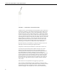
CS650 and CS655 Water Content Reflectometers 1. Introduction The CS650 and CS655 are multiparameter smart sensors that use innovative techniques to monitor soil volumetric water content, bulk electrical conductivity, and temperature. They output an SDI-12 signal that many of our dataloggers can measure. The CS650 has 30 cm length rods, whereas the CS655 has 12 cm length rods. NOTE This manual uses CS650 to reference model numbers CS650 and CS655.
CS650 and CS655 Water Content Reflectometers FIGURE 4-1. CS650 Water Content Reflectometer Volumetric water content information is derived from the probe’s sensitivity to the dielectric permittivity of the medium surrounding the probe stainless-steel rods. The CS650 is configured as a water content reflectometer, with the two parallel rods forming an open-ended transmission line.
CS650 and CS655 Water Content Reflectometers means of RS-232 Tx/Rx. The A200 USB-to-Serial Module allows RS-232 serial communication between a computer and the CS650 by means of Campbell Scientific’s Device Configuration Utility software, DevConfig. The CS650's cable can terminate in: • • Pigtails that connect directly to a Campbell Scientific datalogger (option –PT). Connector that attaches to a prewired enclosure (option –PW). Refer to www.campbellsci.com/prewired-enclosures for more information.
CS650 and CS655 Water Content Reflectometers 5.
CS650 and CS655 Water Content Reflectometers FIGURE 5-1. CS650 and CS655 average current drain FIGURE 5-1 shows average current drain for different measurement rates and quantities of CS650 probes. If the time between measurements is five minutes or longer, average current drain may be approximated at 0.15 milliamps per sensor. 5.3 Operational Specifications CS650 CS655 1 to 81 1 to 81 1 to 40: ±(2% of reading + 0.6) for solution EC ≤3 dS/m ±(3% of reading + 0.
CS650 and CS655 Water Content Reflectometers CS650 CS655 Range: 5% to 50% 5% to 50% Accuracy†: ±3% VWC typical in mineral soils where solution EC ≤3 dS/m ±3% VWC typical in mineral soils where solution EC ≤10 dS/m Precision‡: <0.05% <0.05% Range Solution EC: 0 to 3 dS/m 0 to 8 dS/m Range Bulk EC: 0 to 3 dS/m 0 to 8 dS/m Accuracy†: ±(5% of reading + 0.05 dS/m) ±(5% of reading + 0.05 dS/m) Precision‡: 0.5% of BEC 0.
CS650 and CS655 Water Content Reflectometers 6. Installation 6.1 Orientation and Placement The CS650 measures the bulk dielectric permittivity, average volumetric water content, and bulk EC along the length of the rods, which is 30 cm for the CS650 and 12 cm for the CS655. The probe rods may be inserted vertically into the soil surface or buried at any orientation to the surface. The probe may be installed horizontal to the surface to detect the passing of wetting fronts or other vertical water fluxes.
CS650 and CS655 Water Content Reflectometers FIGURE 6-1. CS650G Insertion Guide Tool 6.3 Wiring CS650 connections to a datalogger are shown below. Dataloggers are divided into those which are programmed with the CRBasic programming language and those that are programmed with Edlog. CRBasic dataloggers include the CR1000, CR3000, CR5000, CR800-series, and CR200X-series. Compatible Edlog dataloggers include the CR10X, CR23X, and CR510. 6.3.
CS650 and CS655 Water Content Reflectometers SDI-12 communication has the advantage that up to ten probes may be given different addresses and share a single control port. Another advantage is that the datalogger programming is much simpler for SDI-12 communication than RS-232. NOTE The orange Rx wire is only used for RS-232 Tx/Rx communication, and should be grounded when using SDI-12. 6.3.2 RS-232 Wiring TABLE 6-2 shows the wiring code for communicating with a CS650 using RS-232 serial protocol.
CS650 and CS655 Water Content Reflectometers NOTE Drivers should be loaded before plugging the A200 into the PC. The A200 drivers can be downloaded, at no charge, from: www.campbellsci.com/downloads. 6.4.1.2 Cabling One end of the A200 has a terminal block while the other end has a type B female USB port. The terminal block provides 12V, G, TX, and RX terminals for connecting the sensor (see FIGURE 6-2 and TABLE 6-2). A data cable, part number 17648, ships with the A200.
CS650 and CS655 Water Content Reflectometers FIGURE 6-2. A200 Sensor-to-PC Interface 6.4.2 Device Configuration Utility (DevConfig) DevConfig may be downloaded from the Campbell Scientific website, www.campbellsci.com/downloads. Connect the CS650 to the A200 as shown in TABLE 6-2. Connect the PC to the A200 USB port with the supplied USB cable. Launch DevConfig and select “CS650 Series” from the Device Type menu on the left. Select 9600 from the Baud Rate drop-down menu.
CS650 and CS655 Water Content Reflectometers Select the appropriate PC Serial Port from the list of available COM ports shown when the browse button on the lower left is selected (see Section 6.4.1.4, Determining which COM Port the A200 has been Assigned). Select Ok and then Connect to begin communication with the CS650.
CS650 and CS655 Water Content Reflectometers 6.4.2.1 Settings Editor Tab The Settings Editor tab shows settings stored in the CS650 firmware. Settings that may be modified include User Name, SDI-12 Address, and RS-232 Baud Rate. Attempts to change any of the other settings will result in a “Commit failed. Unrecognized error condition” error message. DevConfig polls the CS650 every two seconds while connected and the results are displayed in the Real-Time Measurements field.
CS650 and CS655 Water Content Reflectometers Real-Time Measurements 14 Measurement Field Name Meaning VWC Volumetric Water Content EC (dS/m) Bulk Electrical Conductivity TS (°C) Soil Temperature Ka Bulk Dielectric Permittivity PA (µS) Period Average VR Voltage Ratio
CS650 and CS655 Water Content Reflectometers 6.4.2.2 Send OS Tab The Send OS tab is used to update the firmware in the CS650. The firmware is available at www.campbellsci.com/downloads. The file to send will have a filename extension of .a43, such as CS65X.Std.00.36.a43. Sending a new operating system will not affect any of the user-modified settings or probe specific multiplier and offset settings. To download a new operating system, follow the Operating System Download Procedure listed on the Send OS tab.
CS650 and CS655 Water Content Reflectometers 6.4.2.3 Terminal Tab The Terminal tab may be used to send serial commands directly to the CS650. See TABLE 6-3 for a list of serial interface commands. To send a command from the Terminal tab, left click in the field to get a flashing black cursor, then press several times until the CS650> prompt is shown. At the prompt, type in the command then .
CS650 and CS655 Water Content Reflectometers TABLE 6-3.
CS650 and CS655 Water Content Reflectometers TABLE 6-4.
CS650 and CS655 Water Content Reflectometers The proper sequence in the datalogger program for measuring CS650 probes on a multiplexer is: 1. Set RES control port high to enable multiplexer 2. Pulse CLK control port to advance to next multiplexer channel 3. Set switched 12 volt channel high to supply power to CS650 4. Send SDI-12 command(s) to CS650 5. Set switched 12 volt channel low to remove power from CS650 6. Repeat steps 2 – 5 for each CS650 connected to the multiplexer 7.
CS650 and CS655 Water Content Reflectometers 6.6.2 CR1000 With 2 CS650 Probes on Same Control Port This CRBasic example program measures two CS650 probes on a CR1000 every 15 minutes, storing hourly averages of volumetric water content, electrical conductivity, and soil temperature and samples of permittivity, period average and voltage ratio. The first CS650 has a SDI-12 address of 0 and the second an address of 1. Wiring for the example is shown in TABLE 6-6.
CS650 and CS655 Water Content Reflectometers TABLE 6-7. Wiring For Program Example 3 CR1000 AM16/32B (2x32 mode) 12V 12V G GND C2 RES C3 CLK SW12 COM ODD H C1 COM ODD L G COM Ground CS650 High Channels 1H – 12H Red Low Channels 1L – 12L Green Ground Channels to Left of Low Channels Black, Orange, Clear Code Example 3.
CS650 and CS655 Water Content Reflectometers TABLE 6-8. Wiring For Program Example 4 CR10X CS650 12V Red C1 Green G Black, Orange, Clear Code Example 4. Edlog Code: CR10X Program to Measure a Single CS650 Probe ;{CR10X} ;Inloc labels ;1 VWC ;2 EC ;3 Tsoil_C ;4 Ka ;5 PerAvg ;6 VR *Table 1 Program 01: 900 Execution Interval (seconds) 1: SDI-12 Recorder (P105) 1: 0 SDI-12 Address 2: 3 Start Measurement (aM3!) 3: 1 Port 4: 1 Loc [ VWC ] 5: 1.0 Multiplier 6: 0.
CS650 and CS655 Water Content Reflectometers TABLE 6-9. Wiring For Program Example 5 CR10X CS650’s (wiring same for both) 12V Red C1 Green G Black, Orange, Clear Code Example 5.
CS650 and CS655 Water Content Reflectometers 6.6.6 CR200X With 3 CS650 Probes This CRBasic example program measures 3 CS650 probe on a CR200X every 15 minutes, storing hourly averages of volumetric water content, electrical conductivity, soil temperature, permittivity, period average, and voltage ratio. The CS650’s have SDI-12 addresses of 0, 1, and 2. Sensors are powered with the SWBatt channel which requires a 3 second warm-up time.
CS650 and CS655 Water Content Reflectometers 7. The Water Content Reflectometer Method for Measuring Volumetric Water Content 7.1 Description of Measurement Method For the water content measurement, a differential emitter-coupled logic (ECL) oscillator on the circuit board is connected to the two parallel stainless steel rods.
CS650 and CS655 Water Content Reflectometers It is important to distinguish between soil bulk electrical conductivity and soil solution electrical conductivity. Soil solution electrical conductivity refers to the conductivity of the solution phase of soil. Soil solution electrical conductivity, σsolution can be determined in the laboratory using extraction methods to separate the solution from the solid and then measuring the electrical conductivity of the extracted solution.
CS650 and CS655 Water Content Reflectometers 7.4 Error Sources in Water Content Reflectometer Measurement 7.4.1 Probe-to-Probe Variability Error All manufactured CS650s/CS655s are checked in standard media to develop a probe specific span and offset value for electrical conductivity and dielectric permittivity measurements. These probe specific values are written to the probe’s firmware and minimize probe-to-probe variability. 7.4.
CS650 and CS655 Water Content Reflectometers 7.5.1 Accurate Soil Temperature Measurement The thermistor used for measuring soil temperature is located in the probe head and is in contact with one of the stainless steel rods. In order to make an accurate soil temperature measurement, the probe head should be buried in the soil so that it is insulated from diurnal temperature fluctuations. 8. Water Content Reflectometer User-Calibration 8.
CS650 and CS655 Water Content Reflectometers A minimum of four data points are required for derivation of a 3rd degree polynomial. Data points should be spaced as evenly as practical over the expected range of water content and include the wettest and driest expected values. 8.3 Collecting Laboratory Data for Calibration Water content reflectometer data needed for CS650 calibration are the CS650 permittivity reading and an independently determined volumetric water content.
CS650 and CS655 Water Content Reflectometers The container to hold the soil during calibration should be non-metal and large enough that the rods of the probe are no closer than about 10 cm from any container surface. Pack the container as uniformly as possible in bulk density with relatively dry soil (volumetric water content <10%). Probe rods can be buried in a tray or inserted into a column. When using a column, insert the rods carefully through surface until rods are completely surrounded by soil.
CS650 and CS655 Water Content Reflectometers Gravimetric water content is calculated after the container mass is accounted for. θg = m wet − m dry m dry For the bulk density ρ bulk = m dry volume cylinder the dry mass of the sample is divided by the sample tube volume.
CS650 and CS655 Water Content Reflectometers A vertical face of soil can be formed with a shovel. If the CS650 is to be used within about 0.5 meters of the surface, the probe can be inserted into the face and water added to the surface with percolation. After adding water, monitor the CS650 permittivity to determine if the soil around the rods is at equilibrium. With soil at equilibrium, record the CS650 permittivity. Soil hydraulic properties are spatially variable.
CS650 and CS655 Water Content Reflectometers The volumetric water content is the product of the gravimetric water content and the bulk density θ v = θ g * ρ bulk The average water content for the replicates and the recorded CS650 period are one datum pair to be used for the calibration curve fit. 8.5 Calculations The empty cylinders used for core sampling should be clean and both empty mass and volume are measured and recorded.
CS650 and CS655 Water Content Reflectometers 10.
CS650 and CS655 Water Content Reflectometers 11. References Ledieu, J., P. De Ridder, P. De Clerck, and S. Dautrebande. 1986. “A method of measuring soil moisture by time-domain reflectometry,” J. Hydrol. 88:319-328. Rhoades, J.D., P.A.C. Raats, and R.J. Prather. 1976. Effects of liquid-phase electrical conductivity, water content and surface conductivity on bulk soil electrical conductivity. Soil Sci. Soc. Am. J., 40: 651-653. Rhoades, J.D., N.A. Manteghi, P.J. Shouse, W.J. Alves. 1989.
CS650 and CS655 Water Content Reflectometers 36
Appendix A. Discussion of Soil Water Content The water content reflectometer measures volumetric water content. Soil water content is expressed on a gravimetric and a volumetric basis. To obtain the independently determined volumetric water content, gravimetric water content must first be measured. Gravimetric water content (θg) is the mass of water per mass of dry soil. It is measured by weighing a soil sample (mwet), drying the sample to remove the water, then weighing the dried soil (mdry).
Appendix B. SDI-12 Sensor Support B.1 SDI-12 Command Basics SDI-12 commands have three components: Sensor address (a) – a single character, and is the first character of the command. CS650 sensors are usually assigned a default address of zero unless option –VS is selected at the time of ordering. Sensors with the –VS option are addressed with the last digit of the probe’s serial number.
Appendix B. SDI-12 Sensor Support Change Address Command (aAb!) Sensor address is changed with command aAb!, where a is the current address and b is the new address. For example, to change an address from 0 to 2, the command is 0A2! The sensor responds with the new address b, which in this case is 2. Send Identification Command (aI!) Sensor identifiers are requested by issuing command aI!.
Appendix B. SDI-12 Sensor Support Aborting a Measurement Command A measurement command (M!) is aborted when any other valid command is sent to the sensor. Send Data Command (aDv!) This command requests data from the sensor. It is normally issued automatically by the datalogger after measurement commands aMv! In transparent mode, the user asserts this command to obtain data.
Appendix B. SDI-12 Sensor Support The following examples show how to use LoggerNet software to enter transparent mode and change the SDI-12 address of a CS650 sensor. The same steps are used to enter transparent mode with PC200W and PC400 software after accessing the terminal emulator as previously described. B.2.2 CR200(X) Series Datalogger Example 1. Connect a single CS650 to the datalogger as follows: • Green to Control Port C1/SDI12 • Black, Orange, Clear to G • Red to Battery + 2.
Appendix B. SDI-12 Sensor Support address. To exit SDI-12 transparent mode select the Close Terminal button. B.2.3 CR1000 Datalogger Example 1. Connect a single CS650 to the datalogger as follows: • Green to Control Port C1 • Black, Orange, Clear to G • Red to 12V 2. In the LoggerNet Connect screen navigate to the Datalogger menu and select Terminal Emulator. The “Terminal Emulator” window will open.
Appendix B. SDI-12 Sensor Support 6. To change the SDI-12 address, key in aAb! where a is the current address from the above step and b is the new address. The CS650 will change its address and the datalogger will respond with the new address. To exit SDI-12 transparent mode, press the Esc key or wait for the 60 second timeout, then select the Close Terminal button. B.2.4 CR10X Datalogger Example 1.
Appendix B. SDI-12 Sensor Support FIGURE B-3. SDI-12 transparent mode on CR10X datalogger using control port 1 and changing SDI-12 address from 0 to 1 B.2.5 CR10X-PB Table-Based Datalogger Example 1. Connect a single CS650 to the datalogger as follows: • Green to Control Port C1 • Black, Orange, Clear to G • Red to 12V 2. Download a datalogger program that contains the SDI-12 Recorder (P105) instruction with valid entries for each parameter.
Appendix B. SDI-12 Sensor Support 8. To change the SDI-12 address, enter the command aAb!; where a is the current address from the above step and b is the new address. The CS650 will change its address and the datalogger will exit the SDI-12 Transparent Mode. 9. Activate the SDI-12 Transparent Mode on Control Port 1 again by entering *8#1 . Verify the new SDI-12 address by entering the ?! command. The CS650 will respond with the new address. 10. To exit the SDI-12 Transparent Mode, type in *0.
Campbell Scientific Companies Campbell Scientific, Inc. (CSI) 815 West 1800 North Logan, Utah 84321 UNITED STATES www.campbellsci.com • info@campbellsci.com Campbell Scientific Africa Pty. Ltd. (CSAf) PO Box 2450 Somerset West 7129 SOUTH AFRICA www.csafrica.co.za • cleroux@csafrica.co.za Campbell Scientific Australia Pty. Ltd. (CSA) PO Box 8108 Garbutt Post Shop QLD 4814 AUSTRALIA www.campbellsci.com.au • info@campbellsci.com.au Campbell Scientific do Brasil Ltda. (CSB) Rua Apinagés, nbr.