INSTRUCTION MANUAL DCP100 Data Collection Platform 2/99 C o p y r i g h t ( c ) 1 9 9 9 C a m p b e l l S c i e n t i f i c , I n c .
Warranty and Assistance The DCP100 DATA COLLECTION PLATFORM is warranted by CAMPBELL SCIENTIFIC, INC. to be free from defects in materials and workmanship under normal use and service for twelve (12) months from date of shipment unless specified otherwise. Batteries have no warranty. CAMPBELL SCIENTIFIC, INC.'s obligation under this warranty is limited to repairing or replacing (at CAMPBELL SCIENTIFIC, INC.'s option) defective products.
WARNINGS FOR DCP100 USERS 1. The datalogger operating system must be compatible for use with the TGT-1. CR10X dataloggers must have version 1.6 or later. All CR510 datalogger operating systems are compatible with the DCP100. CR500 dataloggers need version 1.4 or later. CR23X dataloggers should have version 1.4 or later. CR10 and 21X dataloggers require a special PROM. CR10 PROM is item number 8131-00, 21X PROM is item number 8132-04. Check *B mode for operating system version.
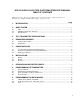
DCP100 DATA COLLECTION PLATFORM OPERATOR’S MANUAL TABLE OF CONTENTS PDF viewers note: These page numbers refer to the printed version of this document. Use the Adobe Acrobat® bookmarks tab for links to specific sections. PAGE 1. INTRODUCTION.........................................................................................................................1 2. GOES SYSTEM ..........................................................................................................................1 2.
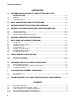
TABLE OF CONTENTS APPENDICES A. INFORMATION ON ELIGIBILITY AND GETTING ONTO THE GOES SYSTEM................................................................................................................ A-1 A.1 A.2 Eligibility.................................................................................................................................. A-1 Acquiring Permission ............................................................................................................. A-1 B.
TABLE OF CONTENTS 6.3-3 6.3-4 G-1 G-2 G-3 H-1 H-2 I-1 I-2 I-3 I-4 I-5 I-6 Antenna Mounting Hardware, Assembled View 2......................................................................6 Example Antenna Orientation Diagram......................................................................................7 Magnetic Declination for the Contiguous United States.........................................................G-1 Declination Angles East of True North ..............................................
TABLE OF CONTENTS This is a blank page.
DCP100 DATA COLLECTION PLATFORM OPERATOR'S MANUAL 1. INTRODUCTION The DCP100 combines the measurement and control capabilities of Campbell Scientific’s dataloggers with the broad geographic coverage afforded by GOES (Geogstationary Operational Environmental Satellite) telemetry. Satellite telemetry offers a convenient telecommunication alternative for field stations where phone lines or RF systems are impractical.
DCP100 DATA COLLECTION PLATFORM NESDIS Wallops Station, VA ground station has 10 asynchronous dial-up circuits Computer Base Station DCP100 Data Collection Platform Yagi antenna Environmental enclosure Phone modem Phone line NESDIS Wallops Station, VA ground station has 10 asynchronous dial circuits communication/power cable Antenna cable Transmitter Datalogger Power supply FIGURE 2-1. Data Retrieval Diagram 3. TGT1 TRANSMITTER SPECIFICATIONS • Phone modem with MNP level 4 error correction.
ASLFJO AKD ASLFJO AKD ASLFJO AKD ASLFJO AKD UNITED tryu to read this whoever ASLFJO AKD ASLFJO AKD ASLFJO AKDASLFJO AKD ASLFJO AKD ASLFJO AKD AKD AKD ASLFJO AKDASLFJO AKD ASLFJO ASLFJO ASLFJO AKDASLFJO AKD ASLFJO AKD ASLFJO AKD ASLFJO AKD ASLFJO AKD ASLFJO AKD ASLFJO AKD ASLFJO AKD ASLFJO AKD ASLFJO AKD ASLFJO AKD ASLFJO AKD ASLFJO AKD ASLFJO AKD ASLFJO AKD BATT DESI PAK. DESI PAK.
DCP100 DATA COLLECTION PLATFORM 5. POWER SUPPLIES 5.1 12 AND 24 AHR SEALED RECHARGEABLE BATTERIES Typically, the system is powered with a 12 Volt, 12 AHr sealed rechargeable battery that connects to a charging regulator and a solar panel. The 12 AHr battery lasts 15 to 20 days per charge. A 24 AHr sealed rechargeable battery which lasts 30 to 40 days is available. NOTE: This assumes the data are transmitted for 30 seconds at 3 hour intervals.
DCP100 DATA COLLECTION PLATFORM TABLE 6.1-1 Wiring Diagram SC925G Cable 25-Pin connector connects to TGT1 I/O port Black connects to CH12R (Ground) Red connects to CH12R +12 Terminal 9-Pin connector connects to datalogger I/O port Antenna Cable BNC male connector connects to TGT1 BNC female port Red Cable Connects to CH12R +12 and datalogger 12 V Black Cable Connects to CH12R and datalogger G (Ground) FIGURE 6.3-1.
DCP100 DATA COLLECTION PLATFORM Fits onto the 1.5" OD pipe FIGURE 6.3-2. Antenna Mounting Hardware, Assembled View 1 Fits onto the 1.5" OD pipe FIGURE 6.3-3.
DCP100 DATA COLLECTION PLATFORM GOES SATELLITE s) ile m 3 2, (2 00 DATA COLLECTION PLATFORM ANTENNA 36 (Elevation Angle) S (180 ) 213 (Azimuth Angle) W (270 ) E (90 ) N (360 ) EXAMPLE ORIENTATION FIGURE 6.3-4. Example Antenna Orientation Diagram 7. FORWARD AND REFLECTED POWER Forward and reflected power are measured (in decimal units) and updated during each transmission (see Sections 8 and 9).
DCP100 DATA COLLECTION PLATFORM 8. PROGRAMMING THE TRANSMITTER 8.1 STAR POUND MODE The star/pound (*#) mode is for programming the transmitter. It establishes and edits parameters, displays status information, and performs test transmissions. The *# mode can only be accessed via a keyboard/display (not with a computer). TABLE 8.2-1. *# Parameter's Descriptions Parameter Description 1-3 Set the transmitter's clock. All scheduled operations are referenced to this clock.
DCP100 DATA COLLECTION PLATFORM 18 - 20 Random transmission interval (the NESDIS-assigned time period that the transmission is randomly repeated, minimum interval is 5 minutes). Parameter 18 is hours; 19 is minutes and 20 is seconds. 21 - 23 Set the time of the initial self-timed transmission (NESDIS-assigned). The “initial” time is not the first time but an offset. Self-timed transmissions occur on multiples of the self-timed transmission interval plus the offset.
DCP100 DATA COLLECTION PLATFORM the “A” key is pressed. The active buffer is set using command 7 and 8. 3 Forward power is the first parameter and reflected power is the second (see Section 7). 4 The first parameter displays the number of errors. Parameters 2-9 list the history of errors, where parameter 2 is the most recent (see Section 8.4). 5 Number of bytes in self-timed or random buffer (used after command 6 or 7). 6 Selects self-timed buffer (used before command 5).
DCP100 DATA COLLECTION PLATFORM 9.1.2 Datalogger Programming Theory Campbell Scientific dataloggers are programmed via a keyboard/display or an IBMPC compatible computer running PC208 software. Please see the appropriate datalogger manual for detailed programming information.
DCP100 DATA COLLECTION PLATFORM ;Set Output Flag High (10) for daily output. 11: If time is (P92) 1: 0 Minutes (Seconds --) into a 2: 1440 Interval (same units as above) 3: 10 Set Output Flag High ;Timestamp data 12: Real Time (P77) 1: 220 Day,Hour/Minute (prev day at midnight, 2400 at midnight) ;Average, maximize, and minimize the reference and thermocouple temperatures, the battery voltage, and the forward and reflected power readings.
DCP100 DATA COLLECTION PLATFORM TABLE 9.2-1. P123 Parameter Descriptions Parameter Number Description 1-8 The NESDIS-assigned address. Convert the letters in the address to their decimal equivalent (Table 8.22). Each digit of the address is placed in one parameter. 09 NESDIS-assigned self-timed uplink channel (see Appendix E channel/ frequency correlation). If not assigned a self-timed channel, type in zeros. 10 NESDIS-assigned random uplink channel (see Appendix E for channel/ frequency correlation).
DCP100 DATA COLLECTION PLATFORM 03: ID Where: ID>0 9.3 21X 9.3.1 Instruction 99 The array ID for the data that is transferred to the TGT1's buffer. Theory The 21X's Instruction 99 is the same as the CR10X’s Instruction 120, except there is an extra parameter that specifies the array of data that is transferred to the TGT1 buffer. Instruction 99 also automatically compares the datalogger and transmitter's clocks.
DCP100 DATA COLLECTION PLATFORM ;{21X} ; *Table 1 Program 01: 10.0 Execution Interval (seconds) ;Measure reference temperature. 01: Internal Temperature (P17) 1: 1 Loc [ RefTemp ] ;Measure thermocouple temperature. 02: Thermocouple Temp (DIFF) (P14) 1: 1 Reps 2: 1 ± 5 mV Slow Range 3: 5 DIFF Channel 4: 1 Type T (Copper-Constantan) 5: 1 Ref Temp Loc [ RefTemp ] 6: 2 Loc [ TCDef_F ] 7: 1.8 Mult 8: 32 Offset ;Transfer data to TGT1 every hour.
DCP100 DATA COLLECTION PLATFORM transfer time for the hourly data initiated by the P99 in instruction 10.
APPENDIX A. INFORMATION ON ELIGIBILITY AND GETTING ONTO THE GOES SYSTEM A.1 ELIGIBILITY U.S. federal, state, or local government agencies, or users sponsored by one of those agencies, may use GOES. Potential GOES users must receive formal permission from NESDIS. A.2 ACQUIRING PERMISSION 1. The user contacts NESDIS at the following address and submits a formal request to transmit data via GOES. Non-U.S.
APPENDIX B.
APPENDIX C. ANTENNA ORIENTATION COMPUTER PROGRAM (WRITTEN IN BASIC) 5 6 10 20 30 40 45 50 60 70 80 90 100 110 115 120 130 140 150 155 160 170 180 190 200 210 220 300 310 320 330 340 350 360 370 380 400 460 REM THIS PROGRAM CALCULATES THE AZIMUTH AND ELEVATION FOR AN REM ANTENNA USED WITH A DCP FOR GOES SATELLITE COMMUNICATIONS CLS : CLEAR 1000 INPUT "SATELLITE LONGITUDE (DDD.DD)"; SO INPUT "ANTENNA LONGITUDE (DDD.DD)"; SA PRINT "ANTENNA LATITUDE (DDD.
APPENDIX D. DETAILED FORWARD/REFLECTED POWER INFORMATION D.1 IMPEDANCE MATCHING TABLE D.2-1. Pout Values The reflected power to forward power ratio shows the degree of impedance match between the transmitter and the cable/antenna assembly. The percent of power reflected approximates the impedance match with the following equation: FWD 110 130 150 165 175 185 195 205 215 230 250 2 % power reflected = [((ref + 17.4)/(fwd + 17.
APPENDIX D. DETAILED FORWARD/REFLECTED POWER INFORMATION 04: 05: 06: Z=X*Y (P36) 1: 10 2: 10 3: 10 X Loc [ Scratch1 ] Y Loc [ Scratch1 ] Z Loc [ Scratch1 ] Z=X*F (P37) 1: 10 2: 100 3: 10 16: Else (P94) X Loc [ Scratch1 ] F Z Loc [ Scratch1 ] 17: Z=X+F (P34) 1: 10 2: -1 3: 7 Z=F (P30) 1: 0 2: 0 3: 6 X Loc [ Scratch1 ] F Z Loc [ PerRef ] 18: 15: Z=X+F (P34) 1: 11 2: 20.
APPENDIX E. CHANNEL/FREQUENCY CORRELATION Channel 1 2 3 4 5 6 7 8 9 10 11 12 13 14 15 16 17 18 19 20 21 22 23 24 25 26 27 28 29 30 31 32 33 34 35 36 37 38 39 40 41 42 43 44 45 46 47 48 49 Frequency (MHz) 401.7010 401.7025 401.7040 401.7055 401.7070 401.7085 401.7100 401.7115 401.7130 401.7145 401.7160 401.7175 401.7190 401.7205 401.7220 401.7235 401.7250 401.7265 401.7280 401.7295 401.7310 401.7325 401.7340 401.7355 401.7370 401.7385 401.7400 401.7415 401.7430 401.7445 401.7460 401.7475 401.7490 401.
APPENDIX E. CHANNEL/FREQUENCY CORRELATION 100 101 102 103 104 105 106 107 108 109 110 111 112 113 114 115 116 117 118 119 120 121 122 123 124 125 126 127 128 129 130 131 132 133 134 135 136 137 138 139 140 141 142 143 144 145 146 147 148 149 E-2 401.8495 401.8510 401.8525 401.8540 401.8555 401.8570 401.8585 401.8600 401.8615 401.8630 401.8645 401.8660 401.8675 401.8690 401.8705 401.8720 401.8735 401.8750 401.8765 401.8780 401.8795 401.8810 401.8825 401.8840 401.8855 401.8870 401.8885 401.8900 401.
APPENDIX F. DATA DUMP DATALOGGER PROGRAM F.1 INTRODUCTION The data dump program inserts 20 data points (60 bytes) into the transmitter's random buffer when user FLAG 1 is manually toggled HIGH. The buffer is cleared when the user FLAG 2 is set HIGH. F.2 TOGGLING USER FLAG 1 HIGH You start by typing in *6AD to enter the FLAG Status Mode. [00:00:00:00] is displayed, indicating user FLAGS 1 through 8 are set low. To toggle user FLAG 1 HIGH, type 1. After the display shows [10:00:00:00], type *0.
APPENDIX F. DATA DUMP DATALOGGER PROGRAM ;Clear Random buffer to prevent random transmissions. 08: Data Transfer to GOES (P120) 1: 11 random buffer/overwrite the old data 2: 1 FWD/Ref Power Loc [ Data ] 09: 10: Do (P86) 1: 22 Set Flag 2 Low End (P95) F.7 21X DATA DUMP PROGRAM The 21X's program is the same as the CR10X and CR10's, except Instruction 99 has an extra parameter. With this parameter, you specify the array of data that is transferred to the buffer (see Section 9.2).
APPENDIX G. LOCAL MAGNETIC DECLINATION A general map showing magnetic declination for the contiguous United States is shown in Figure G-1. Magnetic declination for a specific site can be obtained from a USGS map, local airport, or through a computer service offered by the USGS called GEOMAG (recommended). Section G.2 has a listing of the prompts and the declination determined by GEOMAG for a site near Logan, Utah. G.
APPENDIX G. LOCAL MAGNETIC DECLINATION Options: Annual change: 1 = Field Values (D, I, H, X, Z, F) 2 = Magnetic Pole Positions 3 = Dipole Axis and Magnitude 4 = Magnetic Center [1] : 1 0 -6.1 Display values twice Name of field model return Date return Latitude Longitude Elevation Units (m/km/ft) [N]: press return [USCON90]: press [current date]: press The declination in the example above is listed as 15 degrees and 59.6 minutes. Expressed in degrees, this would be 15.99 degrees.
APPENDIX H. CHANGING THE CR10'S RAM OR PROM CHIPS This section describes changing the CR10’s PROM, not the CR10X’s. The CR10X already contains the Instructions for the DCP100. straighten it and repeat the installation procedure. H.2.1 CHANGING JUMPERS The CR10 has two sockets for Random Access Memory (RAM) and one socket for Programmable Read Only Memory (PROM). The standard CR10 has 64K of RAM, (a 32K RAM chip in each socket). Earlier CR10s had 16K of RAM (an 8K RAM chip in each socket). H.
APPENDIX H. CHANGING THE CR10'S RAM OR PROM CHIPS FIGURE H-1. Disassembling CR10 FIGURE H-2.
APPENDIX I. 21X PROM REPLACEMENT PROCEDURE This appendix covers the procedure for replacing the firmware (PROM) in a Campbell Scientific 21X or 21XL Micrologger. For a nominal fee, Campbell Scientific will install PROMs in 21X(L)s that are returned to the factory; request a Returned Materials Authorization (RMA) from Campbell Scientific. CAUTION: This procedure erases data and programs stored in the 21X or 21XL.
APPENDIX I. 21X PROM REPLACEMENT PROCEDURE 1 Firmware Socket A Socket B Socket C OSX-0.1 OSX-1.1 OSX-2.1 6145-03 6145-03 6145-03 6146-05 6146-05 6146-05 6147-06 6160-05 6161-06 Panasonic Panasonic Pannasonic Panasonic 2 NOTE: Older 21X(L) Microloggers, pre 1986, were shipped with only two 4K RAM chips (p/n 6116). When these Microloggers are upgraded to new software PROMs, you must replace the two 4K chips with five 8K chips (p/n 6264). You may also need to reset two jumpers.
APPENDIX I. 21X PROM REPLACEMENT PROCEDURE 12. Hold the new PROM by either end as shown in Figure I-6. Position the PROM over the sockets with the circular notch on the end of the PROM oriented the same direction as the surrounding PROMs. 84 19 146 6 C No o m lN IteObjs FIGURE I-6. Inserting the New PROM CAUTION: The notch must be on the right side. Inserting the PROM in the wrong direction can damage it. Set the pins of the PROM on the individual sockets and press gently.
APPENDIX J.
This is a blank page.
Campbell Scientific Companies Campbell Scientific, Inc. (CSI) 815 West 1800 North Logan, Utah 84321 UNITED STATES www.campbellsci.com info@campbellsci.com Campbell Scientific Africa Pty. Ltd. (CSAf) PO Box 2450 Somerset West 7129 SOUTH AFRICA www.csafrica.co.za sales@csafrica.co.za Campbell Scientific Australia Pty. Ltd. (CSA) PO Box 444 Thuringowa Central QLD 4812 AUSTRALIA www.campbellsci.com.au info@campbellsci.com.au Campbell Scientific do Brazil Ltda.