EnviroSMART™ Soil Water Content Profile Probes Revision: 3/09 C o p y r i g h t © 2 0 0 2 - 2 0 0 9 C a m p b e l l S c i e n t i f i c , I n c . EnviroSMART™, EasyAG®, and IrriMAX® are trademarks of Sentek Pty. Ltd.
Warranty and Assistance The EnviroSMART™ SOIL WATER CONTENT PROFILE PROBES are warranted by CAMPBELL SCIENTIFIC, INC. to be free from defects in materials and workmanship under normal use and service for twelve (12) months from date of shipment unless specified otherwise. Batteries have no warranty. CAMPBELL SCIENTIFIC, INC.'s obligation under this warranty is limited to repairing or replacing (at CAMPBELL SCIENTIFIC, INC.'s option) defective products.
EnviroSMARTTM Table of Contents PDF viewers note: These page numbers refer to the printed version of this document. Use the Adobe Acrobat® bookmarks tab for links to specific sections. 1. General .........................................................................1 2. Absolute Data...............................................................1 3. Relative Data ................................................................1 4. Measurements.............................................................
EnviroSMARTTM Table of Contents B. Normalization and Function Test........................... B-1 B.1 Normalization...................................................................................... B-1 B.1.1 Water Content Only................................................................... B-2 B.1.2 TriSCAN Normalization............................................................ B-4 B.2 Configuration Testing.......................................................................... B-5 C.
EnviroSMARTTM Soil Water Content Profile Probes 1. General EnviroSMARTTM probes measure a profile of volumetric soil water content. EnviroSMART probes measure at 10 cm increments from soil surface to 2 m. 2 meter probes are limited to 16 sensors. TriSCAN versions of these probes also measure soil salinity. Irrigation scheduling, waste water treatment, and other applications requiring continuous monitoring of water or water and ion movement in a soil profile may benefit from EnviroSMART technology.
EnviroSMARTTM Soil Water Content Profile Probes 4.1 Water Content Sensor output is a dimensionless frequency (raw count) that is converted via a normalization equation and then a default or user-defined calibration equation into volumetric soil water content. The measurement unit is volumetric water content (Vol %) or millimetres of water per 100 mm of soil. Acceptable data range for scaled frequencies is >0 to 1.0. Water content measurements using the default calibration range from 0 to 53%. 4.
EnviroSMARTTM Soil Water Content Profile Probes VIC can be related directly to a site-specific soil EC through the use of Sentek’s Benchmarking Procedure. The accuracy of any such relationships are dependent upon the accuracy and competency with which this procedure is performed. In Sentek’s own field testing, strong relationships (r2=0.9) have been achieved. Refer to the benchmarking section of the Sentek TriSCAN manual. Precise temperature effects on salinity data output are currently unknown.
EnviroSMARTTM Soil Water Content Profile Probes 6.
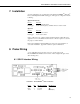
EnviroSMARTTM Soil Water Content Profile Probes 7. Installation Several configurations are possible when using the EnviroSMARTTM / EasyAG® Probes with Campbell Scientific dataloggers.
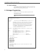
EnviroSMARTTM Soil Water Content Profile Probes 8.2 Cable Installation Securely tighten the gland nut through which the cable passes into the probe cap. Inject a small amount of silicon sealant into the sensor end of the cable to ensure that water or water vapor will not pass into the probe. 9. Datalogger Programming Example program corresponds to setup example in Appendices A and B. Sample CR1000 Program Shaded portions of program can be omitted if TriSCAN sensor options are not used.
EnviroSMARTTM Soil Water Content Profile Probes ‘Program Control Variables Dim X ‘Definition of DataTables DataTable (ES1_SF,1,-1) Sample (1,ES1_ID,FP2) Sample (8,ES1_SF(1),FP2) Sample (8,ES1_VIC(1),FP2) Totalize (1,Rain_mm,FP2,False) Sample (1,Irrig_mm,FP2) EndTable DataTable (ES1_WC,1,-1) Sample (8,ES1_WC(1),FP2) EndTable ‘Program BeginProg ‘Set Probe ID ES1_ID = 101 ‘Set Scan Interval Scan (30,Sec,3,0) ‘Preload Inactive Sensor Error (covers all missing sensors) For X = 1 to 8 step 1 ES1_SF(X) = -1000 ES
EnviroSMARTTM Soil Water Content Profile Probes Else If ES1_SF(X) < -999 Then ES1_WC(X) = -99999 Else ES1_WC(X) = ((ES1_SF(X) - c)/a)^(1/b) EndIf EndIf Next X ‘...OR... ‘If a WC sensor fails (indicated by ‘-1000) ‘Load NAN for water content ‘...OR... ‘apply calibration ‘Measure rain PulseCount (Rain_mm,1,2,2,0,.
EnviroSMARTTM Soil Water Content Profile Probes ;Wiring: ; ; EnviroSMART / EasyAG 12 Volts (Pin 1) -------- CR10X 12 V EnviroSMART / EasyAG Ground (Pin 2) ------- CR10X Ground EnviroSMART / EasyAG Signal (Pin 3) --------- C7 ; ; Rain Gage Pulse Out -------------------------------- CR10X P2 Rain Gage Ground----------------------------------- CR10X Ground ;{CR10X} ; *Table 1 Program 01: 30 Execution Interval (seconds) ;Load Scaled Frequency to Water Content Co-effecients a = .1957 b = .404 c = .
EnviroSMARTTM Soil Water Content Profile Probes 7: If (X<=>F) (P89) 1: 1 X Loc [ ES1_SF_1 ] 2: 2 <> 3: 0 F 4: 31 Exit Loop if True 8: End (P95) ;Measure salinity volumetric ion content (VIC) 9: Beginning of Loop (P87) 1: 0 Delay 2: 5 Loop Count 10: SDI-12 Recorder (P105) 1: 0 SDI-12 Address 2: 2 Start Measurement (aM2!) 3: 7 Port 4: 17 Loc [ ES1_VIC_1 ] 5: 1.
EnviroSMARTTM Soil Water Content Profile Probes 17: If (X<=>F) (P89) 1: 1 X Loc [ ES1_SF_1 ] 2: 4 < 3: -9999 F 4: 30 Then Do ;If 1st sensor reading is < -9999 i.e.
EnviroSMARTTM Soil Water Content Profile Probes 28: Z=X^Y (P47) 1: 9 -- X Loc [ ES1_WC_1 ] 2: 34 Y Loc [ RecipB ] 3: 9 -- Z Loc [ ES1_WC_1 ] 29: End (P95) 30: End (P95) ;End If ;End If 31: End (P95) ;Next Loop ;Measure Rain 32: Pulse (P3) 1: 1 2: 1 3: 2 4: 25 5: .
EnviroSMARTTM Soil Water Content Profile Probes 40: Sample (P70) 1: 1 Reps 2: 26 Loc [ Irrig_mm ] ;Output Water Content Data to Storage 41: Do (P86) 1: 10 Set Output Flag High (Flag 0) 42: Set Active Storage Area (P80) 1: 1 Final Storage Area 1 2: 201 Array ID 43: Real Time (P77) 1: 1220 Year,Day,Hour/Minute (midnight = 2400) 44: Sample (P70) 1: 8 Reps 2: 9 Loc [ ES1_WC_1 ] *Table 2 Program 02: 0.
EnviroSMARTTM Soil Water Content Profile Probes 28 _________ 0 0 0 29 C 110 30 A 110 31 _________ 0 0 0 32 B 110 33 _________ 0 0 0 34 RecipB 1 1 1 10. Care and Maintenance Probe electronics will be damaged if exposed to water or condensation. A proper installation must include active desiccant in the cap of each probe. Be certain the gland nut through which the cable passes is tight.
Appendix A. Probe Assembly FIGURE A-1. Finished EnviroSMARTTM Assembly Figure A-1 shows a finished three-sensor probe. Your probe may require more or less than three sensors at different spacing. FIGURE A-2. Probe Rod Top Remove the probe rod from the access tube by removing the plug on one end of the tube. The plug can be removed by shaking the tube vertically such that the rod internally hammers on the plug and eventually dislodges it. Identify the “top” as indicated in Figure A-2. FIGURE A-3.
Appendix A. Probe Assembly “Loosely” attach the handle to the rod with two of the large screws that came with the assembly as shown in Figure A-3. FIGURE A-4. Location of Small Main Board Screws FIGURE A-5. Securing Main Board Electrical Connection Install the main board assembly as shown in Figure A-4 between the two sides of the mounting rail. The header is plugged into the first connector in the rail as shown in Figure A-5.
Appendix A. Probe Assembly FIGURE A-7. Sensor Orientation FIGURE A-8. Sensor Ribbon Cable Determine the number and locations of sensors that are to be installed. They may or may not be as indicated in the example in Figure A-6. Place the first sensor carefully over the rail, oriented as shown in Figure A-7. To advance the sensor assembly to its location on the rail, press and hold the spot indicated by the arrow in Figure A-8.
Appendix A. Probe Assembly FIGURE A-10. Aligning Sensor Tab with Probe Slot FIGURE A-11. Plugging in Ribbon Cable Header Advance the sensor to its proper location. Align and snap the lock ring in place. Insert a screwdriver as shown in Figure A-9 and pull outward on the screwdriver after carefully aligning the tab with its slot in the rail, as shown in Figure A-10. After snapping in place, carefully plug the header on the ribbon cable into its proper connector in the rail as shown in Figure A-11.
Appendix A. Probe Assembly FIGURE A-13. Location of Addressing Jumpers FIGURE A-14. Location of Jumper 1 FIGURE A-15.
Appendix A. Probe Assembly FIGURE A-16. Location of Jumpers 1..16 After positioning and securing each sensor in its proper location, install the jumpers on the ribbon cable boards. Begin at the main board end and install the jumpers on each sensor board in numeric sequence as shown in Figure A-12. Locate the sensor jumper pins as shown in Figure A-13. Set sensor 1 jumper to the first position as shown in Figure A-14. Set sensor 2 jumper to the second position as shown in Figure A-15.
Appendix B. Normalization and Function Test Normalization is the setting of the range over which the electronics is effective. This range is bounded by the two extremes of air and water. B.1 Normalization Connect +12 Volts DC and ground to the green connector at the top of the probe as shown in Figure B-1. FIGURE B-1. SDI-12 Interface Power Connection Connect the Intelligent Probe Utility Cable (P/N SEN06020) to the TTL port near the top of the probe at the location indicated in Figure B-2. FIGURE B-2.
Appendix B. Normalization and Function Test Start the IPConfig Utility (Intelligent Probe Utility Software, P/N SEN06025) on the PC by clicking on the IPConfig Utility icon (shown in Figure B-3). FIGURE B-3. IPConfig Utility Icon Click “Connect” in the upper right area of the IPConfig window. The software will connect to the probe and set up a configuration window. B.1.1 Water Content Only FIGURE B-4.
Appendix B. Normalization and Function Test 1. Click on “Auto-detect Sensors” in the lower left corner. Wait until all sensors are auto-detected. If the number of sensors detected does not correspond with the number of sensors on the probe, check to ensure that each sensor is addressed sequentially, beginning with address 1 on the top sensor. 2. Enter the depth of each sensor in the “Depth” column. Each depth will be a multiple of 10. 3. Enter “1.000000;1.000000;0.
Appendix B. Normalization and Function Test B.1.2 TriSCAN Normalization When normalizing TriSCAN sensors for water content, follow the procedure in B.1.1 using distilled or deionized water in step 5. As illustrated in Figure B-5, the same procedure is followed when normalizing TriSCAN sensors for salinity. FIGURE B-5.
Appendix B. Normalization and Function Test B.2 Configuration Testing FIGURE B-6. IPConfig Configuration Test Window Test the configuration by going to the “Configuration Test” tab as shown in Figure B-6. Again, with the probe in the access tube, hold the probe in the air, then press “Query All Sensors.” Press “Stop Sensor Querying” when values appear in the window. Raw counts should be close to the values shown in the example above.
Appendix B. Normalization and Function Test This is a blank page.
Appendix C. Access Tube Installation The information below is a summary. Further information is provided in the Sentek Diviner2000® Installation Guide Version 1.0, available as a .PDF file from Campbell Scientific, Inc. Sensors must be installed correctly into the soil medium. The soil around the sensor needs to be representative of the rest of the field. The aim of the installation is to cause minimum disturbance to the crop and soil profile.
Appendix C. Access Tube Installation C.1 Standard Access Tube Installation C.1.1 Installation Tools Toolkit items Installation Toolkit No. 1 Items ordinarily required 1 x Regular Auger 47.0 mm 1 x Auger Cleaning Tool (small) 2 x Auger Extension Rods 0.5 m 3 x Auger Extension Rods 1.0 m 1 x Regular T-handle 2 x Tommy Bars 1 x Access Tube Cleaning Tool No. 1 – spiral 1 x Access Tube Cleaning Tool No. 2 – foam 1 x Access Tube Cleaning Tool No. 3 – rag tool 1 x Access Tube Cleaning Tool No.
Appendix C. Access Tube Installation C.1.2 Installing the Access Tube Figure C-1. Incorrect Installation To install the access tube, follow these steps (requires tool kits #1 and #2): 1. Put on the gloves. 2. Put on the safety goggles. 3. Select the 47 mm regular auger head. 4. Select the required extension rods and screw the auger head and the t-handle to the extension rods. The length of assembled auger must exceed the length of the access tube by at least 20 cm. 5.
Appendix C. Access Tube Installation 11. Use a sledgehammer to tap the dolly until the access tube is embedded approximately 5-10 cm into the soil. 12. Place the auger inside the access tube and turn the auger handle. Auger ahead of the access tube by approximately 20 cm (until the pen mark made in Step 6 is flush with the top of the access tube). 13. Take the auger out of the tube and empty the soil using the small auger cleaning tool no. 1. 14. Select dolly no. 1 or dolly no.
Appendix C. Access Tube Installation 5. Select Access Tube Cleaning Tool no. 3 — rag tool. Insert a clean cotton cloth into the eyelet and saturate with denatured alcohol. Move this tool up and down the access tube to clean off the final dirt residue from the access tube. 6. After cleaning the tube, use a flashlight to inspect the inside of the access tube. You should be able to see clean walls and the lip of the cutting edge at the bottom. C.1.
Appendix C. Access Tube Installation 5. Wipe off excess silicon from the inside of the access tube. 6. Screw the cap back onto the top cap housing. C.2 Access Tube Removal Requires took kits #1 and #3. 1. Unscrew the top cap. 2. Attach t-handle and bung tightening tool to the required auger extension rods. 3. Use tommy bars to tighten t-handle and bung tightening tool firmly to the extension rods. 4. Insert this tool into the access tube until you feel the top of the bottom stopper bung. 5.
Appendix C. Access Tube Installation 16. Winch the access tube carefully upward and out of the ground. 17. Remove the access tube from the extraction tripod for cleaning and storage. 18. To separate the top cap assembly base from the access tube, silicon can be loosened with the hot air stripper and the components cleaned with acetone. FIGURE C-2. Installation Toolkit #1 FIGURE C-3.
Appendix C. Access Tube Installation This is a blank page.
Appendix D. Site Selection Site selection is a critical process for all soil water sensors. A properly selected site will reflect changes in soil moisture and plant water use trends over a larger area. This area may be an entire field, sub-section of a field, a crop variety, a planting, a soil type, etc. Putting a sensor in a ‘dry zone’ or under the influence of a malfunctioning sprinkler will invalidate data. Site selection is carried out by identifying macro-zones and micro-zones.
This is a blank page.
Appendix E. SDI-12 Commands The SDI-12 EnviroSMART probe interface communicates with Campbell Scientific dataloggers by way of SDI-12 protocol. A complete treatment of SDI-12 communications for the EnviroSMART is available from Sentek or Campbell Scientific in the EnviroSMART & EasyAG SDI-12 Probe Interface Manual. Commonly used commands are listed below. Refer to Edlog and CRBasic help for information on how to use these commands while programming Campbell Scientific dataloggers.
This is a blank page.
Campbell Scientific Companies Campbell Scientific, Inc. (CSI) 815 West 1800 North Logan, Utah 84321 UNITED STATES www.campbellsci.com • info@campbellsci.com Campbell Scientific Africa Pty. Ltd. (CSAf) PO Box 2450 Somerset West 7129 SOUTH AFRICA www.csafrica.co.za • cleroux@csafrica.co.za Campbell Scientific Australia Pty. Ltd. (CSA) PO Box 444 Thuringowa Central QLD 4812 AUSTRALIA www.campbellsci.com.au • info@campbellsci.com.au Campbell Scientific do Brazil Ltda.