INSTRUCTION MANUAL NL120 Ethernet Module Revision: 3/14 C o p y r i g h t © 2 0 0 6 - 2 0 1 4 C a m p b e l l S c i e n t i f i c , I n c .
Warranty “PRODUCTS MANUFACTURED BY CAMPBELL SCIENTIFIC, INC. are warranted by Campbell Scientific, Inc. (“Campbell”) to be free from defects in materials and workmanship under normal use and service for twelve (12) months from date of shipment unless otherwise specified in the corresponding Campbell pricelist or product manual. Products not manufactured, but that are re-sold by Campbell, are warranted only to the limits extended by the original manufacturer.
Assistance Products may not be returned without prior authorization. The following contact information is for US and international customers residing in countries served by Campbell Scientific, Inc. directly. Affiliate companies handle repairs for customers within their territories. Please visit www.campbellsci.com to determine which Campbell Scientific company serves your country. To obtain a Returned Materials Authorization (RMA), contact CAMPBELL SCIENTIFIC, INC., phone (435) 227-9000.
Table of Contents PDF viewers: These page numbers refer to the printed version of this document. Use the PDF reader bookmarks tab for links to specific sections. 1. Introduction ................................................................. 1 2. Cautionary Statements ............................................... 1 3. Initial Inspection ......................................................... 1 4. Quickstart .................................................................... 2 4.1 4.
Table of Contents ii
NL120 Ethernet Module 1. Introduction Campbell Scientific’s NL120 Ethernet Module enables 10Base-T Ethernet communications. It allows the datalogger to communicate over a local network or a dedicated Internet connection via TCP/IP. This small, rugged communication device connects to the 40-pin peripheral port on a CR1000 or CR3000 datalogger. This manual describes how to use LoggerNet to connect to your datalogger with an NL120 attached.
NL120 Ethernet Module 4. Quickstart This section describes the basics of communicating via Ethernet with the NL120. 4.1 Physical Setup CAUTION Always power down the datalogger before installing or removing the NL120 to or from the datalogger. After powering down the datalogger, plug the NL120 into the datalogger peripheral port (see FIGURE 4-1). Attach Ethernet cable to the 10Base-T port.
NL120 Ethernet Module d. Press the Apply button to save the changes and then close the Device Configuration Utility. NOTE A temporary IP address may be obtained from a DHCP server. For more information, see Section 6.8, DHCP. NOTE The NL120 must be connected to the datalogger before configuring the datalogger with the Device Configuration Utility. If it is not connected, the TCP/IP settings will not be displayed. 4.2.
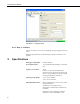
NL120 Ethernet Module FIGURE 4-2. LoggerNet setup 4.2.3 Step 3 – Connect You are now ready to connect to your datalogger using the LoggerNet Connect screen. Datalogger program transfer, table-data display, and data collection are now possible. 5. Specifications Datalogger Compatibility: CR1000, CR3000 Power Requirements: 12 V supplied through datalogger’s peripheral port Typical Current Drain: 20 mA (Note: To save power, the IPNetPower() instruction can be used to turn off power to the NL120.
NL120 Ethernet Module Cable Requirements: Use a straight-through Ethernet cable when the cable is run from the hub to the NL120. Use a crossover Ethernet cable when the cable is run directly from the computer to the NL120. Use a shielded Ethernet cable and/or the 28033 surge suppressor when the cable length is greater than 9 ft. Software Requirements: LoggerNet 3.2 or later PC400 1.3 or later Dimensions: 10.2 x 6.4 x 2.8 cm (4.0 x 2.5 x 1.1 in) Weight: 66.6 g (2.35 oz) FIGURE 5-1.
NL120 Ethernet Module 6.1 Communicating over TCP/IP Once the datalogger, the NL120, and LoggerNet have been set up as described in Sections 4.1, Physical Set-up, and 4.2, Communicating via Ethernet, communication is possible over TCP/IP. This includes program send and data collection. These are straightforward operations and are accomplished through LoggerNet’s Connect screen. For more information, see the LoggerNet manual.
NL120 Ethernet Module 6.1.2 Datalogger-to-Datalogger Communication Communication between dataloggers is possible over TCP/IP. In order to do this, a socket must be opened between the two dataloggers. This is done using the TCPOpen() instruction. The socket opened by this instruction is then used by the instructions performing datalogger-to-datalogger communication. The example program below gets the battery voltage from a remote datalogger and sends its panel temperature to the remote datalogger.
NL120 Ethernet Module Records Display must be manually refreshed. In addition, links are provided to all HTML files, all XML files, and all JPEG files in the datalogger. FIGURE 6-1. Datalogger home page If there is a default.html file on the datalogger, this will automatically become the user-configurable home page. The WebPageBegin/WebPageEnd declarations and the HTTPOut instruction can be used in a datalogger program to create HTML or XML files that can be viewed by the browser.
NL120 Ethernet Module FIGURE 6-2. FTP root directory FIGURE 6-3.
NL120 Ethernet Module In order to use FTP, the datalogger’s FTP User Name and FTP Password must be set. This is done using Device Configuration Utility. 6.3.1.1 Step 1 – Configure Datalogger NOTE a. Connect serial cable from PC COM port to datalogger RS-232 port. b. Open Campbell Scientific’s Device Configuration Utility. Select the device type of the datalogger (CR1000 or CR3000), the appropriate Serial Port, and baud rate. Connect to the datalogger. c.
NL120 Ethernet Module PROGRAM 'CR1000 'FTPClient.cr1 Public Result1, Result2 BeginProg Scan (20,Sec,1,1) Result1 = FTPClient("192.168.7.85","user","password","USR:pic.jpg","USR:pic.jpg",0) Result2 = FTPClient("192.168.7.85","user","password","USR:file.html”,"USR:file.html",1) NextScan EndProg 6.4 Telnet Telnetting to the datalogger’s IP address allows access to the same commands as the Terminal Emulator in LoggerNet Connect screen’s Datalogger menu. 6.
NL120 Ethernet Module 6.6.2 Serial Output The TCPOpen() instruction must be used first to open up a TCP socket. An example of this instruction is shown below. The first parameter in TCPOpen() is the IP address to open a socket to. The second parameter is the port number to be used. The third parameter is buffer size. The TCPOpen() instruction returns the socket number of the open connection or ‘0’ if it cannot open a connection. socket = TCPOpen(“192.168.7.
Campbell Scientific Companies Campbell Scientific, Inc. (CSI) 815 West 1800 North Logan, Utah 84321 UNITED STATES www.campbellsci.com • info@campbellsci.com Campbell Scientific Africa Pty. Ltd. (CSAf) PO Box 2450 Somerset West 7129 SOUTH AFRICA www.csafrica.co.za • cleroux@csafrica.co.za Campbell Scientific Australia Pty. Ltd. (CSA) PO Box 8108 Garbutt Post Shop QLD 4814 AUSTRALIA www.campbellsci.com.au • info@campbellsci.com.au Campbell Scientific do Brasil Ltda. (CSB) Rua Apinagés, nbr.