
User guide
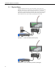
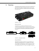
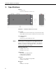
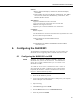
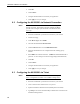
Table Of Contents
- Revision and Copyright Information
- Limited Warranty
- Assistance
- Precautions
- Table of Contents
- 1. Introduction
- 2. Cautionary Statements
- 3. Quickstart
- 4. Overview
- 5. Specifications
- 6. Configuring the NL200/201
- 7. Operation
- 8. Applications
- 9. Troubleshooting
- 10. Attribution
- Appendix A. Glossary
- Appendix B. Cables, Pinouts, LED Function, and Jumper
- Appendix C. NL200/201 Settings
- Appendix D. Sending a New OS to the NL200/201
- Campbell Scientific Companies
NL200/201 Network Link Interface
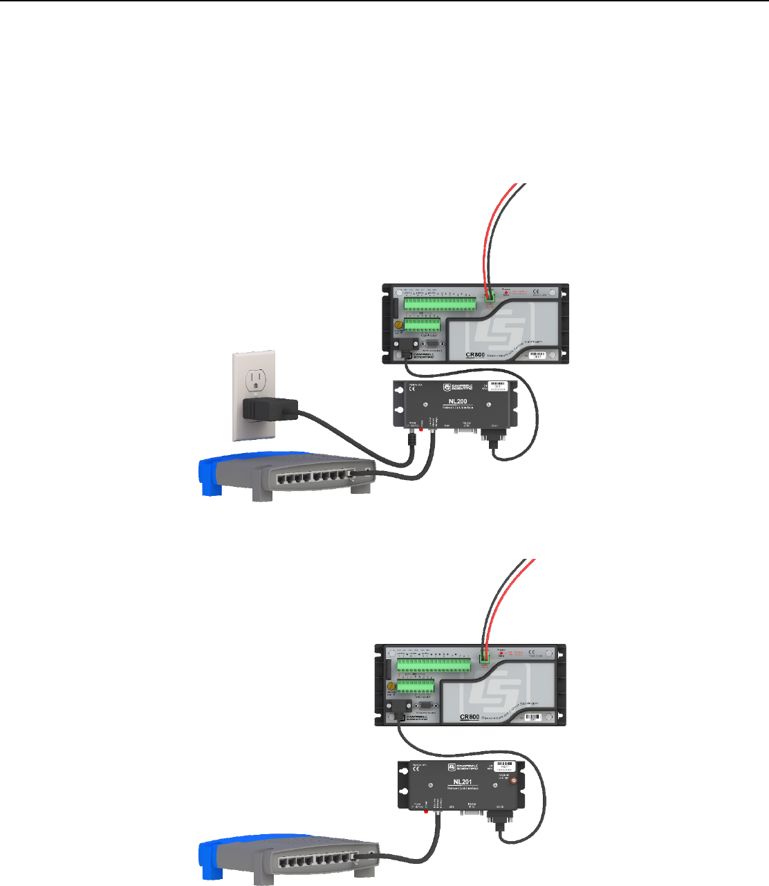
3.1 Physical Setup
Using the supplied serial cable, connect the NL201’s CS I/O port to the
datalogger’s CS I/O port. Alternatively, power the NL200 or NL201 through
the barrel-connector jack located on the edge of the device. Connect the
NL200/201 to your network using an Ethernet cable, attaching one end of the
cable to the NL200/201’s Ethernet port and the other end to your network.
Ensure that the device is powered up by inspecting the Power LED.
FIGURE 3-1. NL200 with CR800 (external power)
FIGURE 3-2. NL201 with CR800 (powered by datalogger)
2