
User guide
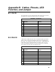
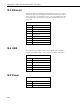

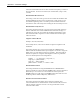
Table Of Contents
- Revision and Copyright Information
- Limited Warranty
- Assistance
- Precautions
- Table of Contents
- 1. Introduction
- 2. Cautionary Statements
- 3. Quickstart
- 4. Overview
- 5. Specifications
- 6. Configuring the NL200/201
- 7. Operation
- 8. Applications
- 9. Troubleshooting
- 10. Attribution
- Appendix A. Glossary
- Appendix B. Cables, Pinouts, LED Function, and Jumper
- Appendix C. NL200/201 Settings
- Appendix D. Sending a New OS to the NL200/201
- Campbell Scientific Companies
Appendix B. Cables, Pinouts, LED
Function, and Jumper
B.1 CS I/O
The CS I/O cable is a 9-pin, straight-through cable with all 9 pins connected.
The supplied SC12 cable (part number 16675) is recommended.
TABLE B-1. CS I/O Pinout
Pin
Datalogger (DB9 Female)
Function
Peripheral (DB9 Male)
Function
1 5 VDC N/C
2 SIGNAL GND SIGNAL GND
3 RING RING
4 RXD TXD
5 ME ME
6 SDE SDE
7 CLK/HS CLK/HS
8 12 VDC N/C
9 TXD RXD
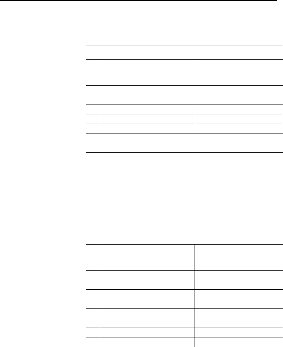
B.2 RS-232
A DB9 female to DB9 male cable (such as Campbell Scientific part number
10873) is used to connect the NL200/201’s RS-232 port to the datalogger’s
RS-232 port. The supplied SC12 cable can also be used. A DB9 female null
modem cable (such as Campbell Scientific part number 13657) is used to
connect the NL200/201’s RS-232 port to a PC’s RS-232 port. The RS-232
cable should be kept short when using high baud rates.
TABLE B-2. RS-232 Pinout
Pin
Datalogger (DCE, DB9 Female)
Function
Peripheral (DTE, DB9 Male)
Function
1
DCD
DCD
2
TXD
RXD
3
RXD
TXD
4
DTR
DTR
5
SIGNAL GND
SIGNAL GND
6
DSR
DSR
7
CTS
RTS
8
RTS
CTS
9
RING
RING
B-1