
User guide
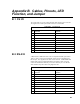
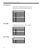
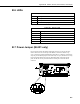

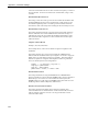
Table Of Contents
- Revision and Copyright Information
- Limited Warranty
- Assistance
- Precautions
- Table of Contents
- 1. Introduction
- 2. Cautionary Statements
- 3. Quickstart
- 4. Overview
- 5. Specifications
- 6. Configuring the NL200/201
- 7. Operation
- 8. Applications
- 9. Troubleshooting
- 10. Attribution
- Appendix A. Glossary
- Appendix B. Cables, Pinouts, LED Function, and Jumper
- Appendix C. NL200/201 Settings
- Appendix D. Sending a New OS to the NL200/201
- Campbell Scientific Companies
Appendix B. Cables, Pinouts, LED Function, and Jumper
B.3 Ethernet
The Ethernet 10Base-T/100Base-TX cable should be a Category 5 or better
twisted pair cable (such as Campbell Scientific part number 13658). The two
active pairs are pins 1 and 2 and pins 3 and 6. Use only dedicated wire pairs
(such as blue/white and white/blue, orange/white and white/orange) for the
active pairs.
TABLE B-3. Ethernet Pinout
Pin Function
1 TD +
2 TD -
3 RD +
4 Not Connected
5 Not Connected
6 RD -
7 Not Connected
8 Not Connected
B.4 USB
The USB cable is the supplied USB A to micro B style cable (Campbell
Scientific part number 27555). This is used only for device configuration.
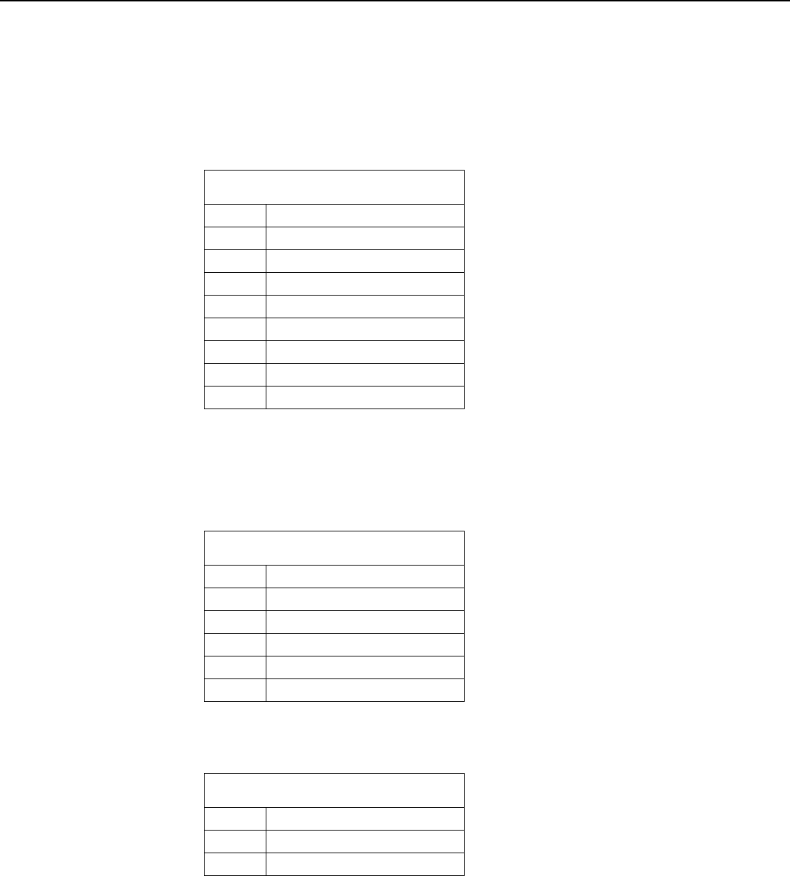
TABLE B-4. USB Micro-B
Pin
Function
1 VBUS (Not Used)
2 Data -
3 Data +
4 N/C
5 GND
B.5 Power
TABLE B-5. Power In
Pin
Function
Center
7 – 20 VDC
Sleeve
Power GND
B-2