PONDVIEW 4.0 CSI AQUACULTURE AUTOMATED MONITORING AND CONTROL SUPPORT SOFTWARE INSTRUCTION MANUAL REVISION: 6/02 COPYRIGHT (c) 2000-2002 CAMPBELL SCIENTIFIC, INC.
This is a blank page.
Limited Warranty CAMPBELL SCIENTIFIC, INC. warrants that the media on which the accompanying computer software is recorded and the documentation provided with it are free from physical defects in materials and workmanship under normal use. CAMPBELL SCIENTIFIC, INC. warrants that the computer software itself will perform substantially in accordance with the specifications set forth in the Operator’s Manual published by CAMPBELL SCIENTIFIC, INC. CAMPBELL SCIENTIFIC, INC.
License for Use This software is protected by both the United States copyright law and international copyright treaty provisions. You may copy it onto a computer to be used and you may make archival copies of the software for the sole purpose of backing-up CAMPBELL SCIENTIFIC, INC. software and protecting your investment from loss. All copyright notices and labeling must be left intact.
PondView Table of Contents PondView Introduction....................................................1 I.1 I.2 I.3 I.4 I.5 Please Read This........................................................................................1 Overview ...................................................................................................1 Installation .................................................................................................1 Uninstall ...................................................
PondView Table of Contents 7. Communication Status ........................................... 7-1 8. Remote Buoy........................................................... 8-1 8.1 Wireless Dissolved Oxygen Probe........................................................ 8-1 8.2 Buoy Parameters ................................................................................... 8-1 9. Troubleshooting......................................................
PondView Introduction I.1 Please Read This Welcome to PondView, Campbell Scientific’s Windows compatible support software for CR10X-TD Monitoring and Control Systems. Please take time to read this manual thoroughly before installing your software. We have designed PondView to be as intuitive as possible, so have intentionally kept this manual short. This manual assumes that the user is familiar with the Microsoft Windows interface.
PondView Introduction If remote PCs are being used to network with the main server computer, then PondView is the only installation that is required. Installation of LoggerNet is only required on the server PC. When prompted to restart the computer select Yes. If insertion of the CD does not initiate the installation process, proceed as follows: From the Windows system menu, select Start | Run. Type D:\Setup.
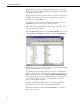
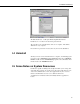
PondView Introduction The Path should read: “ C:\Program Files\Campbellsci\PondView\ PondView.exe” 192.168.22.131 username password 6789 The 192.168.22.131 is the IP address of the server computer. This will be different for every computer. If a username or password is not used, then any word can be substituted. I.4 Uninstall Should you need to remove PondView from a computer, an uninstall program is provided. Select SETTINGS from the Start button then select CONTROL PANEL.
PondView Introduction This is a blank page.
Section 1. Setting Up the Network and Communicating 1.1 Getting Started With the software installed, you are probably anxious to start using PondView. If at all possible, prior to deploying the equipment in the field, make sure you can establish a telecommunication link with the CR10X-TD—even if you have to create a temporary setup in your office. Getting familiar with PondView and your CR10X-TD in the comfort of your office will be a lot less frustrating than trying to resolve problems in the field.
Section 1. Setting Up the Network and Communicating 1.2.2 Configure Communication The Setup Screen is used to configure your CR10X-TD network, define the communication link that exists between the computer and the CR10X-TD, and to set up the data collection schedule. Although many different methods are used for communication between the monitoring system and the PC, the following are the most common methods used. • Direct Connect - Simple serial communication or RAD Short-Haul Modem communication.
Section 1. Setting Up the Network and Communicating then the PakBusPort, then the CR10X-PB, this is the path of communication from the PC to the CR10X-PB. A new device can be added to the network device map by choosing Edit | Add from the Setup menu. The Add Device Window will appear. When you select an item from the left side of the Add Device window, valid connections will be displayed in the right-hand column. Highlight the item to which you want to attach the device and select the Add Now button.
Section 1. Setting Up the Network and Communicating Once all devices are added to the device map, complete the forms associated with each device. Refer to the sections that immediately follow for information on setting up devices. The CR10X-PB is a default label and must be edited. The PondView Software will be looking for a label called CR10XTD_1. After all settings are configured, apply the Setup program by selecting the Apply button; this saves all settings. 1.
Section 1. Setting Up the Network and Communicating 1.3.3.1 Hardware Tab Communication Enable - Before communications can take place, all devices in the chain must be enabled. Maximum Time On-Line - Set to 5 min. Maximum Packet Size - Default 2048 bytes should be used. Extra Response Time - Default 0 ms should be used. Maximum Baud Rate - Default of 9600. Security Code - The CR10X-TD can have a security code to restrict access to the system.
Section 1. Setting Up the Network and Communicating 1.3.3.3 Scheduled Collection Tab The Scheduled Collection tab defines when PondView will automatically collect data from the CR10X-TD. Scheduled Collection Enabled - This check box activates the data collection schedule defined on this tab. This box must be checked. Initial Date - Leave as default date. Initial Time - Set this 10 seconds after the hour. This allows all wireless probes to respond to the CR10X before data collection begins.
Section 1. Setting Up the Network and Communicating 1.3.3.4 Clock Check/Set Tab Automated Clock Check - Enable this to compare the CR10X-TD clock to the server computer’s clock based on the schedule defined by the other parameters on this tab. If the CR10X-TD’s time differs from the PC time by more than a specified amount, the CR10X-TD clock will be set automatically. Enable should be checked. Set the clock initial time to 15 seconds after the hour. All other settings should be left at the default value.
Section 1. Setting Up the Network and Communicating This is a blank page.
Section 2. PondView Display Screen 2.1 Enable the Display PondView is activated by selecting Start|Programs|PondView. When PondView is first started, please be patient. The initialization may take a few minutes. 2.2 Overview Page The Overview Page provides a quick summary of the dissolved oxygen readings in each pond. Ponds are arranged in sections corresponding to the stations that monitor the pond. Each station group includes a time stamp of when the data was collected.
Section 2. PondView Display Screen 2.3 Pond Page The Pond Page provides a desktop display for real-time dissolved oxygen and motor amps, and is used for entering set points for alarms, control of aeration, and sensor calibration.
Section 2. PondView Display Screen 2.4 Temperature Thermometer The temperature thermometer can be use to monitor temperature in degrees Fahrenheit or Celsius. Using the mouse, click on the thermometer the degree units will change to either Celsius or Fahrenheit. 2.5 Trends Seven days of historical data is displayed on the Trends Graph. Select the Trends Graph by using the mouse left button to open the Trends Button .
Section 2. PondView Display Screen This is a blank page.
Section 3. Control Set Points and Alarms 3.1 Control Set Points 3.1.1 Aerator Control The CR10X-TD automatically controls each aerator. If the dissolved oxygen in the pond is below a user-determined value, then the aerator is switched on. If the dissolved oxygen raises to a high set point, the aerator is switched off. Double-click on the pond label (example Pond 1). This will pull up a slider switch that is used to set the low and high points for each aerator in Pond 1.
Section 3. Control Set Points and Alarms 3.2 Alarms PondView provides audio and visual alarms to indicate when critical levels have been reached. These alarms indicate critical levels of dissolved oxygen, aerator motor amps, and communication. To acknowledge the alarm, point to the visual alarm with the mouse and push the right mouse button. An ALARM ACKNOWLEDGE button will appear. Select this button and the audio alarm will be deactivated. Alarms will switch off if the alarm condition on longer exists.
Section 3. Control Set Points and Alarms 3.2.2 Dissolved Oxygen Alarm To select the slider bars for DO alarm set points, double click on the CLICK FOR ALARMS SET POINT box found in the lower right corner. Like the other slider bars, move the bar until the desired set point is found. This enables the alarms for the dissolved oxygen in the ponds. If the DO is lower than the set point, the alarms are activated.
Section 3. Control Set Points and Alarms This is a blank page.
Section 4. Manual Control The automated feature of the CR10X-TD can be overridden using the PondView monitor. Switching aerators on or off can also be accomplished using the on-screen display. 4.1 Aerator Control Click the desired aerator with a right mouse. The Control button will be displayed. Selecting turn on will override the automated conditions of aerator control and turn the aerator on. To switch off aerators that have been switched on, click the desired aerator with the right mouse button.
Section 4. Manual Control This is a blank page.
Section 5. Timer Aerator Control In addition to the aerators being controlled automatically be the condition of the dissolved oxygen, and manually by the operator, they can also be controlled by a timer. Like the manual mode of control, the time mode of control overrides the automated control based on the condition of the dissolved oxygen. The timers will turn the aerator on and off at a user specified time regardless of the condition of the dissolved oxygen. Click on the desired aerator.
Section 5. Timer Aerator Control This is a blank page.
Section 6. DO Probe Calibration 6.1 Dissolved Oxygen Calibration The CR10X-TD is programmed to allow for both automatic dissolved oxygen air calibration and automatic hand calibration of the dissolved oxygen probes. Use whichever method is best for your application. 6.2 Air Calibration Before the air calibration process is enabled the dissolved oxygen probes and temperature sensor must be removed from the water.
Section 6. DO Probe Calibration is to be calibrated. Enter the value obtained using the hand dissolved oxygen meter. Press the Enter key on the PC keypad to send this new value to the CR10X-TD. Once all of the corrected values have been entered into the edit boxes, click the calibration status button with the right mouse. Select Turn On. The CR10X-TD will remain in the Hand Calibration mode for 30 seconds, after which it will automatically return to the Normal operation mode.
Section 7. Communication Status Communication Status (Status Monitor) provides a way to monitor communication statistics for the CR10X-TD network. Information can be viewed on data collection attempts and communication failures. This program is especially useful when using RF communication. From the LoggerNet Tool Bar button select STATUS. Status Monitor is customized to display only those columns containing communication data of interest.
Section 7. Communication Status This is a blank page.
Section 8. Remote Buoy 8.1 Wireless Dissolved Oxygen Probe PondView provides data to view the current conditions of the wireless dissolved oxygen probe. The Buoy is only displayed on your screen if you are using the wireless system. 8.2 Buoy Parameters Use the mouse and right click on the yellow buoy to view the critical parameters of the wireless probe.
Section 8. Remote Buoy This is a blank page.
Section 9. Troubleshooting Problem Solution PondView Screen does not represent my pond lay out. PondView is shipped with a standard .INI file that represents a generic pond lay out. You must replace this generic lay out with one that has been created for your farm. This file is found on the 3-1/2” disk shipped with your equipment. The program on the CR10X-TD has been changed and now the PondView Screen will not communicate. The server is looking for a specific list of labels found on the CR10XTD.
Section 9. Troubleshooting This is a blank page.