QD1 Incremental Encoder Interface Revision: 12/91 C o p y r i g h t © 1 9 8 7 - 1 9 9 1 C a m p b e l l S c i e n t i f i c , I n c .
Warranty and Assistance The QD1 INCREMENTAL ENCODER INTERFACE is warranted by CAMPBELL SCIENTIFIC, INC. to be free from defects in materials and workmanship under normal use and service for twelve (12) months from date of shipment unless specified otherwise. Batteries have no warranty. CAMPBELL SCIENTIFIC, INC.'s obligation under this warranty is limited to repairing or replacing (at CAMPBELL SCIENTIFIC, INC.'s option) defective products.
QD1 Table of Contents PDF viewers note: These page numbers refer to the printed version of this document. Use the Adobe Acrobat® bookmarks tab for links to specific sections. 1. Function........................................................................1 2. Specifications ..............................................................1 3. Connections .................................................................1 4. Datalogger Programming............................................1 4.
This is a blank page.
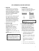
QD1 INCREMENTAL ENCODER INTERFACE 1. FUNCTION The QD1 is designed as a general purpose quadrature decoder to interface CSI's CR10, 21X, and CR7 dataloggers to incremental encoders. This manual focuses on using the QD1 with commercially available shaft encoders used in water level applications (see Appendix). If there are other incremental encoders of interest, please contact CSI's Marketing Department for support.
QD1 INCREMENTAL ENCODER INTERFACE 4.1 POWERING THE QD1 21X and CR7 - 5 VDC must be supplied to the QD1 continuously. When used with the 21X or CR7 dataloggers, a Continuous Analog Output (CAO) port may be programmed to power the QD1. CAO channels are located on the panel of the 21X and the 725 Excitation Card of the CR7. Instructions to send 5 V out the CAO port should occur before the measurement instruction, and must be repeated at least every minute.
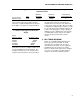
QD1 INCREMENTAL ENCODER INTERFACE TABLE 1. Datalogger Maximum and Minimum Range Limits and Storage Efficiency for Given Output Resolution Low Resolution High Resolution Zero 0.000 0.000 Minimum Magnitude ±0.001 ±0.00001 The resolution of the low resolution format is reduced to 3 significant digits when the first (left most) digit is 7 or greater, as shown in Table 2. TABLE 2. Format Range and Decimal Location for Datalogger Low Resolution Output Range (Absolute Value) 0-6.999 7-69.99 70-699.9 700-6999.
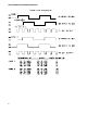
QD1 INCREMENTAL ENCODER INTERFACE FIGURE 1.
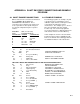
APPENDIX A. SHAFT ENCODER CONNECTIONS AND EXAMPLE PROGRAM A.1 SHAFT ENCODER CONNECTIONS QD1 to shaft encoder connections shown below are for HANDAR's Model 436A and SYNERGETICS's Model 501A. These connections were verified in July of 1987. CSI is not responsible for subsequent changes in encoder pin configurations by the respective vendors.
APPENDIX A.
This is a blank page.
Campbell Scientific Companies Campbell Scientific, Inc. (CSI) 815 West 1800 North Logan, Utah 84321 UNITED STATES www.campbellsci.com info@campbellsci.com Campbell Scientific Africa Pty. Ltd. (CSAf) PO Box 2450 Somerset West 7129 SOUTH AFRICA www.csafrica.co.za sales@csafrica.co.za Campbell Scientific Australia Pty. Ltd. (CSA) PO Box 444 Thuringowa Central QLD 4812 AUSTRALIA www.campbellsci.com.au info@campbellsci.com.au Campbell Scientific do Brazil Ltda.