RDP500 Remote Data Platform Revision: 8/10 C o p y r i g h t © 2 0 0 7 - 2 0 1 0 C a m p b e l l S c i e n t i f i c , I n c .
Warranty and Assistance The RDP500 REMOTE DATA PLATFORM is warranted by Campbell Scientific, Inc. to be free from defects in materials and workmanship under normal use and service for twelve (12) months from date of shipment unless specified otherwise. Batteries have no warranty. Campbell Scientific, Inc.'s obligation under this warranty is limited to repairing or replacing (at Campbell Scientific, Inc.'s option) defective products.
RDP500 Remote Data Platform Table of Contents PDF viewers note: These page numbers refer to the printed version of this document. Use the Adobe Acrobat® bookmarks tab for links to specific sections. 1. Introduction and Theory of Operation .......................1 2. Unpacking RDP500......................................................1 2.1 Parts List ...................................................................................................1 2.1.1 Common Accessories................................
RDP500 Remote Data Platform Table of Contents B.2.3 Send the CRBasic Program – Step 3 ......................................... B-2 B.2.4 Send the CD295/DataView II Configuration – Step 4 .............. B-2 B.3 Change Log ......................................................................................... B-3 C. Exchanging Internal Enclosure Mounting Bracket .C-1 C.1 Introduction ......................................................................................... C-1 C.2 Exchange Process........
RDP500 Remote Data Platform 1. Introduction and Theory of Operation The RDP500 is a Remote Data Platform that provides a versatile measurement system with data storage and control capabilities. When combined with the load-cell option, it may be used to retrofit NWS Fischer-Porter rain gauges to take unattended time-stamped readings. This manual will walk you through the process of using an RDP500.
RDP500 Remote Data Platform (1) RDP500 ENCLOSURE MOUNTING BRACKET [p/n 21921] (1) RDP500 ENCLOSURE BACK PANEL [p/n 21922] (2) NUT ¼”-20 [p/n1132] (4) HRD SCREW 5/16-18 X .750 CAP HEX SS [p/n 4364] (4) HRD SCREW #10-32 X .375 PAN PHILLIPS [p/n 6950] (4) HRD WASHER 5/16 FLAT [p/n 4365] (1) HRD CABLE ENTRY SEAL .110 - .260 ID PG7 W/NUT [p/n 8913] (2) HRD CABLE ENTRY SEAL .187 - .312 ID [p/n 5771] (1) FAB ENC HEYCO CONNECTOR PLUG .
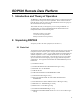
RDP500 Remote Data Platform Zero Adjustment Knob Front Moving End of the Parallelogram FIGURE 3.1-1. Removal of the screws that hold on the pointer. 4. Remove the screw holding the eyelet end of the steel cable from the front movable member of the parallelogram and release the cable. The flexures of the parallelogram mechanism can be damaged if the front arm is side loaded or moved beyond the specified travel. 5. Release the tension spring from the movable support arm (Figure 3.1-2).
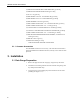
RDP500 Remote Data Platform 6. Take off the punch assembly and tape reel assembly (Figure 3.1-3). FIGURE 3.1-3. Bolts that will be loosened to remove punch assembly and tape reel assembly. 7. Using the overload protection screw, lift the front arm assembly until the parallelogram arms are horizontal (Figure 3.1-4). Overload Protection Screw FIGURE 3.1-4. Adjustment of overload protection screw.
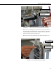
RDP500 Remote Data Platform 8. Unscrew the zero adjustment knob (Figure 3.1-5) until the two loadsupporting helical springs can be taken out (Figure 3.1-6). FIGURE 3.1-5. Unscrewing zero adjustment knob. FIGURE 3.1-6. Removal of helical spring. 9. WARNING Unscrew the rod of the dashpot from the front arm and let it rest on the bottom of the reservoir (Figures 3.1-6 and 3.1-7).
RDP500 Remote Data Platform Dashpot Rod Removal Tool Dashpot Rod FIGURE 3.1-7. The parallelogram is stabilized with one hand while the dashpot rod is unscrewed with the other. 10. Clean the inside of the instrument. 11. Inspect all flexures (leaf springs). There are two pair—one horizontal and one vertical at each fulcrum of the parallelogram (see Figure 3.1-2). 12. Replace the ones that are damaged (broken, bent, kinked or cracked). 13. Check if all screws holding the flexures are tight.
RDP500 Remote Data Platform Gap Gap FIGURE 3.2-1. A gap of ~1/8” left under the bolt heads allows enclosure bracket to slide under bolt head. 3. Install the enclosure assembly onto the base. 4. Align the two keyholes in the bottom of the enclosure bracket over the two bolts; then slide the enclosure to the right until the keyhole slots bottom against the bolts (Figure 3.2.-2). FIGURE 3.2-2. Keyholes aligned over bolts.
RDP500 Remote Data Platform 5. NOTE Using the small 7/16” wrench provided, tighten the two bolts to firmly attach the enclosure to the base. The two bolts are easily accessed through the slots on either side of the enclosure bracket (Figure 3.2-3 and 3.2-4). Slight variability may exist among Fischer/Porter and Belfort rain gauge bases. If the internal enclosure cannot be mounted so that the rain gauge’s outer housing will not slide on, please contact Campbell Scientific, Inc.
RDP500 Remote Data Platform FIGURE 3.2-4. Properly installed internal enclosure. Notice it is slightly shifted to the right. 6. Once the datalogger enclosure is firmly mounted, remove the load cell from the top of the enclosure. 7. Route the load cell from the backside of the support structure and suspend it from the upper hook with the U-bolt bracket facing up. 8.
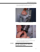
RDP500 Remote Data Platform Flat Blade Screwdriver FIGURE 3.2-5. Flat blade screwdriver turns the gain adjusting screw. 9. Lift the front member of the parallelogram carefully and route the lower hook through the eyebolt and slowly lower the front-end parallelogram. 10. Use the upper hook adjusting nut to shorten the distance between the two hooks so that the weight of the moving end of the parallelogram is supported by the load cell (Figure 3.2-6). FIGURE 3.2-6.
RDP500 Remote Data Platform For optimal operation, the arms of the parallelograms should be horizontal and parallel to the base of the rain gauge. If the front end is too high, lower the shipping bolt and unscrew the adjusting nut on the top hook. If the front end is too low, then tighten the adjusting nut on the top hook. 11.
RDP500 Remote Data Platform 2. Feed the solar panel cable and grounding wire through the plastic compression fitting and brass hex bushing into the base of the rain gauge (Figure 3.3-1). FIGURE 3.3-1. Solar panel cable and grounding wire routed through compression fitting of rain gauge base. 3. Route the solar panel cable through the compression fitting attached to the internal enclosure and up into the PS100 charging source (Figure 3.3-2). Grounding Wire Load Cell Cable Solar Panel Cable FIGURE 3.
RDP500 Remote Data Platform 4. Wire the red and black leads into the terminals labeled “charge” on the PS100 (see wiring diagram at the end of the manual). The polarity of the solar panel is not important. 5. Route the grounding wire to the grounding lug and secure with screw provided. The instruments located inside the internal enclosure are already routed to the grounding lug from the factory. 3.4 Overload Protection Adjustments 1. Install the catch basin tare in the instrument. 2.
RDP500 Remote Data Platform 4. Calibration Instructions A two-point calibration is adequate because the load cell is linear to within 2.5 grams (0.003” rain equivalent). This calibration procedure assumes the user has a properly mounted, level, and fully functional RDP500 weighing style rain gauge. NOTE 1. Begin by removing the top hood from the rain gauge and emptying, drying, and cleaning out the rain gauge catch basin.
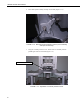
RDP500 Remote Data Platform 4. Carefully reinstall the catch basin and wait for 5 minutes until the “Precip_in” field is stable. This delay is to allow post processing in the datalogger program to sweep from one end of the measurement range to another. 5. The “Precip_in” field can be viewed by pressing enter on the keyboard display two times from its default Campbell Scientific start up screen (Figure 4-2) or by pressing the right arrow key twice on the CD295 external display screen. FIGURE 4-2.
RDP500 Remote Data Platform 7. You must first tare the gauge by selecting “Tare Gauge” under “Step 1”. This will zero out the rain gauge and result in a “Precip_in” value within +/- 0.001” of 0. If the desired results are not achieved, ensure the catch basin is properly mounted and that the rain gauge is level then repeat the steps listed above to re-tare the rain gauge. 8.
RDP500 Remote Data Platform WARNINGS Care should be taken when handling the catch basin and the lower cover of the rain gauge. Sideways pressure applied to the supporting rod will damage the flexures resulting in a need for their replacement. The load cell is sensitive to shocks and overloading. Handle with care. To achieve the best possible performance, the rain gauge must be level and firmly secured. 5. Software The RDP500 includes a datalogger pre-programmed to make the measurements (see Appendix A).
RDP500 Remote Data Platform FIGURE 5.1-1. PC200W Setup/Connect Tab 5.2 DevConfig DevConfig (Device Configuration Utility) is the preferred tool for configuring the CR1000. It is made available as part of LoggerNet, PC400, RTDAQ, and at www.campbellsci.com. Most settings can also be entered through the CR1000KD. Features of DevConfig include: 18 • Communicates with devices via direct RS-232 only. • Sends operating systems to supported device types.
RDP500 Remote Data Platform As shown in Figure 5.2-1, the DevConfig window is divided into two main sections: the device selection panel on the left side and tabs on the right side. After choosing a device on the left, choose from the list of the serial ports (COM1, COM2, etc.) installed on the PC. A selection of baud rates is offered only if the device supports more than one baud rate. The page for each device presents instructions to set up the device to communicate with DevConfig.
RDP500 Remote Data Platform FIGURE 5.2-2. DevConfig OS download window for CR1000. The text at right gives the instructions for sending the OS. Follow these instructions. When the Start button is clicked, DevConfig offers a file open dialog box that prompts for the operating system file (*.obj file). When the CR1000 is then powered-up, DevConfig starts to send the operating system. When the operating system has been sent, a message dialog will appear similar to the one shown in Figure 5.2-3. FIGURE 5.2-3.
RDP500 Remote Data Platform 6. CompactFlash® (CF) CAUTION When installing or removing the CFM100 module, first turn off CR1000 power. Removing a card from the CFM100 while the CF card is active can cause garbled data and can actually damage the card. Always press the button to disable the card for removal and wait for the green LED before switching off the CR1000 power. To prevent losing data, collect data from the CF card before sending a program to the datalogger.
RDP500 Remote Data Platform 7.
RDP500 Remote Data Platform 8.
RDP500 Remote Data Platform 24
Appendix A. CRBasic Program for Version 18 'CR1000 Series Datalogger 'FISCHER & PORTER/BELFORT WEIGHING RAINGAUGE RETROFIT. 'VERSION: RDP500_V18.CR1 'Note: The PRT is not needed to achieve the specification, however it is included in this ' system in an effort to create a sensor-temperature dataset that can be analized by ' any questioning party. 'Change Log: ' 2008-08-08 ' Program released for manual ' 2010-04-20 ' Changed data record interval from 5 min to 15 min.
Appendix A. CRBasic Program for Version 18 Public Public Public Public Public PrecipF_in Precip_in FifteenMinAccum TotFAccum TotAccum 'inches. Precipitation amount in inches 'inches. Rrecipitatoin amount in inches rounded to nearest 1/100th 'inches. Precipitation Accumulation Over 15 min period 'inches. Total precip accumulation 'inches.
Appendix A.
Appendix A. CRBasic Program for Version 18 'Main Program BeginProg 'If an old offset exists in a prior datarecord, then it will be loaded. Otherwise, 'a default value of -0.260829 will be loaded. Lc_mV_Ofst = CalData.Lc_mV_Ofst(1,1) If Lc_mV_Ofst = NaN Then Lc_mV_Ofst = -0.260829 EndIf 'Factory cal = 1/(3.31 mV/V*2.5v/100lbs/435.59237gr/lb) [gr/mV] 'Calibrated with weight and accounting for the leverage amplification 'If an old mV to Gram conversiong exists in a prior datarecord, then it will be loaded.
Appendix A. CRBasic Program for Version 18 'Subtracts electronics offset and convert to grams assuming 9.81 m/s2 acceleration due to gravity. LC_gr=(LC_mV_Avg-Lc_mV_Ofst)*mVtoGram 'Calibrate the raingage with calibration weights in the gauge. This displays as Step 2: If TriggerCalibration = "3289.0" OR TriggerCalibration = "4111.0" OR TriggerCalibration = "6578.0" OR TriggerCalibration = "7400.0" OR TriggerCalibration = "8222.
Appendix A. CRBasic Program for Version 18 'Measure PRT and convert to C and Deg F. 'The PRT was originally included so that we could perform temperature corrections on 'the load cell. However, after several cycles in the temperature chamber, it was found 'that a temperature correction was not necessicary. We left the PRT on the sensor 'so anyone who wanted to could verify our findings. BrHalf3W (PRT_raw,1,mV250C,13,Vx2,2,2500,True,0,250,10,0) PRT (PRT_C,1,PRT_raw,1.0,0) PRT_F=((PRT_C)*1.
Appendix B. Updating RDP500 Software B.1 Introduction During the lifetime of the RDP500, software updates and enhancements may become available. The user can take advantage of those updates by completing a few simple steps outlined below. B.2 Update Process The update process can be performed using Campbell Scientific's free software package PC200W. Depending on the update made available, the end user may need to execute one or more of the following steps. 1. Back up the RDP500 2.
Appendix B. Updating RDP500 Software B.2.3 Send the CRBasic Program – Step 3 The RDP500 includes a CR1000 pre-programed to acquire and store measurements. The program instructions are written using the CRBasic programming language. The program may be updated using PC200W or Device Configuration Utility. Using PC200W, establish communications with the CR1000 by following Section 5.1 (PC200W Software). Send the program by selecting the Clock / Program tab and clicking the Send Program button. Locate the .
Appendix B. Updating RDP500 Software Connect the CD295 to the computer using a NULL modem cable. Open Device Configuration Utility and select CD295 in the Device Type menu. Select the correct PC Serial Port and click Connect. Click Send Program and use the file dialog to locate and open the .DV2 file to be sent. Reconnect the CD295 to the CR1000 RS232 port. B.3 Change Log July 15, 2010: • Operating system updated to CR1000.Std.20.obj See revision history, 2010 July 09, at http://www.campbellsci.
Appendix B.
Appendix C. Exchanging Internal Enclosure Mounting Bracket C.1 Introduction A replacement mounting bracket may be required for RDP500 units shipped prior to August of 2010. The new bracket provides additional clearance between the RDP500 enclosure and the lower access door of the rain gauge housing. C.2 Exchange Process The equipment required for the exchange includes the items below.
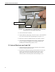
Appendix C. Exchanging Internal Enclosure Mounting Bracket Facing the CD295, slide the enclosure to the left and lift to remove. Place the enclosure face down on a clean surface next to the rain gauge. Use the 1/2” wrench to remove the four bolts securing the mounting bracket to the fiberglass enclosure, then remove the mounting bracket from the back of the fiberglass enclosure.
Appendix C.
Appendix C. Exchanging Internal Enclosure Mounting Bracket Align the replacement bracket to the back of the fiberglass enclosure. Ensure that the tab is oriented towards the bottom of the fiberglass enclosure. Reinstall the four bolts previously removed, securing the new mounting bracket.
Appendix C. Exchanging Internal Enclosure Mounting Bracket Reinstall the enclosure onto the rain gauge base. See Section 3.2, steps 3 through 5, for installation instructions. Ensure the enclosure is installed so that the parallelogram tab lies below the ship tab on the enclosure mounting bracket.
Appendix C. Exchanging Internal Enclosure Mounting Bracket Ensure that the load cell and parallelogram are properly aligned and oriented. Ensure the load cell is vertical and bearing the weight of the moving end of the parallelogram. The arms of the parallelogram should be horizontal and parallel to the base of the rain gauge. See Section 3.2, steps 8 through 14, for detailed information on load cell and parallelogram alignment.
Campbell Scientific Companies Campbell Scientific, Inc. (CSI) 815 West 1800 North Logan, Utah 84321 UNITED STATES www.campbellsci.com • info@campbellsci.com Campbell Scientific Africa Pty. Ltd. (CSAf) PO Box 2450 Somerset West 7129 SOUTH AFRICA www.csafrica.co.za • cleroux@csafrica.co.za Campbell Scientific Australia Pty. Ltd. (CSA) PO Box 444 Thuringowa Central QLD 4812 AUSTRALIA www.campbellsci.com.au • info@campbellsci.com.au Campbell Scientific do Brazil Ltda.