Radiotelemetry Network Revision: 3/00 C o p y r i g h t © 1 9 8 9 - 2 0 0 0 C a m p b e l l S c i e n t i f i c , I n c .
Warranty and Assistance The RADIOTELEMETRY NETWORK COMPONENTS are warranted by CAMPBELL SCIENTIFIC, INC. to be free from defects in materials and workmanship under normal use and service for twelve (12) months from date of shipment unless specified otherwise. Batteries have no warranty. CAMPBELL SCIENTIFIC, INC.'s obligation under this warranty is limited to repairing or replacing (at CAMPBELL SCIENTIFIC, INC.'s option) defective products.
RADIOTELEMETRY NETWORK TABLE OF CONTENTS PDF viewers note: These page numbers refer to the printed version of this document. Use the Adobe Acrobat® bookmarks tab for links to specific sections. PAGE 1. GENERAL RADIOTELEMETRY NETWORK 1.1 1.2 1.3 1.4 Introduction............................................................................................................................. 1-1 Field Station .........................................................................................................
RF MANUAL TABLE OF CONTENTS 4. OPERATION OF THE RADIOTELEMETRY NETWORK 4.1 4.1.1 4.1.2 4.1.3 4.1.4 4.2 Monitoring and Collecting Data - PC208W RF Notes............................................................ 4-1 Basic Concepts ...................................................................................................................... 4-1 Using PC208W Setup Window ..............................................................................................
RF MANUAL TABLE OF CONTENTS APPENDIX J. CABLE PIN OUTS AND LED FUNCTION FOR RF95A AND RF300...............................................................................................H-1 GLOSSARY................................................................................................................a LIST OF FIGURES 1-1 1-2 1-3 1-4 3-1 3-2 3-3 3-4 3-5 3-6 3-7 3-8 4.1-1 4.1-2 4.1-3 B-1 B-2 B-3 G-1 I-1 A Basic Radiotelemetry Network .................................................................
RF MANUAL TABLE OF CONTENTS LIST OF EXAMPLES 3-1 3-2 F-1 A Sample Setup Block............................................................................................................ 3-4 Sample Shutdown Block ........................................................................................................ 3-5 Use of the "U" Command .......................................................................................................
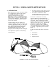
SECTION 1. GENERAL RADIOTELEMETRY NETWORK 1.1 INTRODUCTION Data retrieval from a remote site can be difficult. To accomplish data collection from isolated sites Campbell Scientific, Inc. utilizes a radiotelemetry (RF telemetry) network. Dataloggers can be accessed by RF telemetry which requires no physical connection from the computer to the datalogger. The RF telemetry link reduces the number of visits to a remote site for data collection. The RF telemetry network is designed for complete computer control.
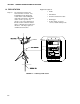
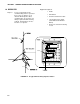
SECTION 1. GENERAL RADIOTELEMETRY NETWORK Equipment Required: 1.2 FIELD STATION Purpose: The field station is where the measurements are made. The Campbell Scientific datalogger resides at this station taking the desired measurements. Any field station can also operate as a repeater. The only requirement is that the station’s antenna must be able to communicate in all desired directions. This may require an omnidirectional antenna.
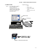
SECTION 1. GENERAL RADIOTELEMETRY NETWORK Equipment Required: 1.3 BASE STATION Purpose: A base station utilizes a computer to collect data from the field station(s). Normally, all communication to the field stations originate at the base station. Data retrieval, remote programming, and system analysis can all be done from the base station.
SECTION 1. GENERAL RADIOTELEMETRY NETWORK Equipment Required: 1.4 REPEATER Purpose: To act as relay between two communicating stations separated by too long of a distance or an obstacle which impedes direct communication. A repeater is not always required in a RF telemetry network. A field station can also function as a repeater.
SECTION 2. ASSEMBLING THE RADIOTELEMETRY NETWORK This section provides a logical order for RF network assembly and deployment. Details of specific components in the system are described in Section 3 “Radiotelemetry Network Components.” Section 3 is cross-referenced throughout this assembly section. 2.1 FINAL LAYOUT The initial locations of the base, field, and repeater stations have likely been determined already. Locate RF stations on an area map, preferably a topographic map.
SECTION 2. ASSEMBLING THE RADIOTELEMETRY NETWORK • REPORT - Generates reports and reduces data stored on computer. • VIEW - Used to view text files. • STG MODULE - Used to service storage modules, SM192 or SM716. • HELP - On line help. Also accessed anywhere by typing F1. PC208W uses a main tool bar to access each of the eight windows. The shape of the main tool bar can be changed using standard Windows methods. Closing the main tool bar closes all other PC208W windows.
SECTION 2. ASSEMBLING THE RADIOTELEMETRY NETWORK Select the Appropriate Communications port. If your computer uses COM2, click the “Add COM port” button to add an RS232 communications port. Next click the “Add Device” button. When the “Add Device” button is clicked the “Add New Device” dialog box opens. Select the RF Modem and attach to the appropriate RS232 communications port. Click OK.
SECTION 2. ASSEMBLING THE RADIOTELEMETRY NETWORK This window shows the RF modem (RF1) attached to RS232 communication port 2. Next use the Add Device button again to connect the datalogger to RF1. This window shows the CR10X datalogger connected to the RF modem. Notice the Dialed Using RF95 path has been set to 10F. The RF95A path is unique to the RF95A dip switch settings.
SECTION 2. ASSEMBLING THE RADIOTELEMETRY NETWORK 2.3 INSTALL NEAREST REPEATER/ FIELD STATION Now to install the nearest field station. If it communicates with the base station via a repeater, the repeater station must also be installed. Following is the order in which a general RF field station should be installed. A repeater station is installed in the same order. For instructions on installing any particular component, refer to either Section 3 of this manual or the Weather Station Manual. 1.
SECTION 2. ASSEMBLING THE RADIOTELEMETRY NETWORK 1. RF modem's ID matches ID in the RF Path. 2. Field station's radio and datalogger have sufficient power. 3. Radio is connected to RF modem. 4. RF modem is the only thing connected to datalogger's 9-pin connector. 2.5.2 ERROR MESSAGES PC208W will log all activity related to each Communications port (COM port). There are two ways to view the messages. On the PC208W main tool bar, click the Status button.
SECTION 2. ASSEMBLING THE RADIOTELEMETRY NETWORK communication path. This will allow you to test each piece of the communication path separately. Try the following TASKs in order. TASK A, Contact RF232A: Press [ENTER] a few times, to set the baud rate between the Base Station's RF modem and the computer. This baud rate can be set at 300, 1200, or 9600 baud. The RF95A will detect the computer’s baud rate and match it. RESPONSE IF SUCCESSFUL: "!" prompt given, SOL modem is now in the Local Command Mode.
SECTION 2. ASSEMBLING THE RADIOTELEMETRY NETWORK This is a blank page.
SECTION 3. RADIOTELEMETRY NETWORK COMPONENTS 3.1.2 RF95A STATES 3.1 RF95A MODEM The RF95A is an interface between the computer and the radio when used at a base station, and an interface between the radio and the datalogger at a field station. In a repeater station, the RF95A is an interface between two other communication stations. The RF95A replaces Campbell Scientific's RF95, DC95 and SDC RF Modems. The RF95A is compatible with previous modems.
SECTION 3. RADIOTELEMETRY NETWORK COMPONENTS TABLE 3-1. A Sample of Station ID Numbers and the Corresponding Switch Settings * Station ID Switch Settings 56789 1234 0 10 20 30 40 50 60 70 80 90 100 110 120 130 0000 0101 0010 0111 0001 0100 0011 0110 0000 0101 0010 0111 0001 0100 0000X 0000X 1000X 1000X 0100X 1100X 1100X 0010X 1010X 1010X 0110X 0110X 1110X 0001X Station ID 255 is reserved for phone-to-RF base stations.
SECTION 3. RADIOTELEMETRY NETWORK COMPONENTS 3.1.6 RF95A MODEM COMMUNICATION PROTOCOL Comprehension of this section is not necessary for routine operation of the RF95A Modem. The PC208W Datalogger Support Software accounts for the necessary communication protocol. There must be an RF95A Modem at both the calling (or computer) end of the transmission link, and at the answer (or datalogger) end of the transmission link.
SECTION 3. RADIOTELEMETRY NETWORK COMPONENTS characters are summarized in Table 3-2. All command characters must be capital letters. TABLE 3-2. RF95A Command Character Summary Command E Sxxx yyy where: Description xxx = Exit Link Command. The "E" command causes the datalogger to drop its ME line and shut down the RF link. ID number of the RF95A which is acting as the repeater in the link. If no repeater is used then xxx is omitted. yyy = ID number of the EOL modem. Fast Command.
SECTION 3. RADIOTELEMETRY NETWORK COMPONENTS occurs between characters, the data block will be closed and transmitted. Most of the time, the SOL modem will be sending command strings which will be answered by the EOL modem and the datalogger. The response from the datalogger is not instantaneous. If a command is sent before the response from the previous command has been received, the current command will be sent and a possible collision of the RF signal may occur.
SECTION 3. RADIOTELEMETRY NETWORK COMPONENTS Appendix H contains the pin out for the radio to modem cables. The mounting bracket also supports a BNC Jack connector from the radio. The coax cable that is required to connect the radio to its antenna should be connected to the radio at this BNC connector. See Section 3.3 for more information on the antenna cable. TABLE 3-4.
SECTION 3. RADIOTELEMETRY NETWORK COMPONENTS 3.2.3 RADIO INSTALLATION The RF300 Radios are shipped from Campbell Scientific mounted on a special bracket with a cable going from the radio to a BNC connector (see Figure 3-3). The following steps will install a radio for a field or repeater station. 1. Secure the radio and its bracket using the four screws from the RF95A Modem's lid. 2.
SECTION 3. RADIOTELEMETRY NETWORK COMPONENTS See Table 3-7 for cable requirements for common antennas. Due to power loss through the cable, the length of coax cable cannot be extended to any desired length. The amount of power loss is dependent on the radio frequency. RG-8A/U will lose approximately 3.1 dB/100 ft. at 200 MHz and 5.0 dB/100 ft. at 400 MHz. Power loss calculations are reviewed in Appendix C. FIGURE 3-6. Type-NM (male), BNC, and Type-NF (female) Connectors FIGURE 3-5.
SECTION 3. RADIOTELEMETRY NETWORK COMPONENTS 3.4 TRIPODS, TOWERS, ENCLOSURES, AND POWER SUPPLIES There are several methods of mounting and housing sensors and other equipment for a station. 3.4.1 TRIPODS AND TOWERS FOR MOUNTING For the different mounting requirements, Campbell Scientific offers the CM6 Tripod, CM10 Tripod, UT10 Tower, and UT30 Tower.
SECTION 3. RADIOTELEMETRY NETWORK COMPONENTS so the two wires can be inserted into the two terminal ports. The red charge light is on when AC power or a solar panel is connected to the PS12. If the input voltage is high enough, the battery will charge even when the datalogger is on. CAUTION: Switch the power to OFF before disconnecting or connecting the power leads to the Wiring Panel. The Wiring Panel and PS12LA are at power ground.
SECTION 3. RADIOTELEMETRY NETWORK COMPONENTS The RF232's 25-pin female port connects to the computer's 25-pin RS232 port. The RF232A's 25-pin port is configured as Data Communications Equipment (DCE) for direct cable connection to Data Terminal Equipment (DTE), such as an IBM-PC serial port. Table 3-9 shows the pin description. TABLE 3-10. RF232A Power Conversions Pins Jumpered 110 VAC 120 VAC 220 VAC 230 VAC 240 VAC 1-3, 2-4 1-3, 2-4 2-3 2-3 2-3 Apply AC 1-4 1-4 1-5 1-4 1-4 3.5.
SECTION 3. RADIOTELEMETRY NETWORK COMPONENTS RF232A TOP VIEW FIGURE 3-8.
SECTION 4. OPERATION OF THE RADIOTELEMETRY NETWORK All field stations can be accessed and monitored from the central base site. Regular visits to the field sites are required to ensure that all sensors are in place, enclosures are dry, solar panel is clean, and that the tripod and antenna are secure. Frequency of visits to the field sites are variable depending on environmental conditions and the sensors utilized.
SECTION 4. OPERATION OF THE RADIOTELEMETRY NETWORK An example of a simple RF path is “32F”. The F is only used when 9600 baud has been selected, see above. The 32 is the value of the dip switch settings inside the RF95A. If your datalogger is using a security code, add the code to the “Security Code” box. 4.1.3 AUTOMATED DATA COLLECTION PC208W One feature of PC208W is automated/scheduled data collection. PC208W can be setup to call each station based on time.
SECTION 4. OPERATION OF THE RADIOTELEMETRY NETWORK 4.1.4 GENERAL COMMUNICATION - PC208W CONNECT WINDOW General communications include: collect data, send and retrieve programs, monitor measurements in real time, graph real time data, etc. PC208W/Connect window supports these general communication tasks. First establish a communication link. This can only be done after the RF communication path has been setup in the Setup Window. To establish a communication link, open the Connect Window.
SECTION 4. OPERATION OF THE RADIOTELEMETRY NETWORK 4.2 DATALOGGER INITIATED COMMUNICATIONS The datalogger can call the computer to initiate data collection, sometimes termed "call back." Instruction 97, Initiate Telecommunications, is used for this purpose. Call back is commonly used to initiate data collection under emergency situations (e.g., water level falls below lower limit). Call back is not the preferred method for routine data collection.
APPENDIX A. SETTING THE STATION ID Each RF95, including the one in the RF base station, must have a unique Station ID. Each RF modem has nine dip switches; the first eight must be set for a particular Station ID. Following is a list of all possible Station IDs with the corresponding setting of the dip switches. Here, 1 represents open, 0 is closed, and X is "don't care." RF95 and RF95A switches are identical.
APPENDIX A.
APPENDIX A.
APPENDIX A.
APPENDIX B. ALTERNATE BASE STATION CONFIGURATIONS The basic base station consists of a computer and the RF232 Base Station. There are other options for a base station including a portable base station, a phone-to-RF base station, and a phone-to-RF base station with measurement capability. The RF95A is used with RF300 radios. The RF95 is used with RF100/200 radios. B.
APPENDIX B. ALTERNATE BASE STATION CONFIGURATIONS RF95A RF300 FIGURE B-1. Portable Base Station B.3 PHONE-TO-RF BASE STATION WITH MEASUREMENT CAPABILITY When it is desired to have a datalogger at a phoneto-RF base station, the datalogger must be a CR10, CR10X, CR23X, CR510, or CR500 and the RF95A must be in the RF95A-SDC State.
APPENDIX B. ALTERNATE BASE STATION CONFIGURATIONS RF95A RF300 FIGURE B-2. Phone-To-RF Base Station RF95A RF300 FIGURE B-3.
APPENDIX B. ALTERNATE BASE STATION CONFIGURATIONS This is a blank page.
APPENDIX C. POWER CALCULATIONS There must be enough transmission power in any RF link to complete communication. The sources of power are the radio and the antennas. Conversely, power is lost both through the cables (coax loss) and over the distance of communication (path loss). The power of the signal received (Signal Power) can be calculated as stated below. The signal power must be greater than -95 dBm (-80 dBm @ 2.4K baud) to have a good radiotelemetry link.
This is a blank page.
APPENDIX D. FUNDAMENTALS OF RADIOTELEMETRY D.1 RADIO WAVES Radiotelemetry is the process of transferring information (data) in the form of radio waves. The data is transferred on a carrier wave which normally has a sinusoidal form. Therefore, the carrier wave can be described entirely by the frequency, amplitude, and phase with respect to a reference. The commonly used term for radiotelemetry, RF, refers to radio frequency, which in actuality is the frequency of the carrier wave.
APPENDIX D. FUNDAMENTALS OF RADIOTELEMETRY Every antenna has a known horizontal and vertical pattern of radiation. The horizontal radiation pattern consists of any segment of a 360 degree circle surrounding the antenna. The horizontal pattern is important to consider when a RF station is to communicate with more than one other RF station. The vertical pattern is the radiating pattern in the upward and downward directions. Any two communicating RF stations must have a minimum level of signal power.
APPENDIX E. RF95A STATES The RF95A Modem operates in one of two separate states. The RF95A can be utilized in either the RF95A-ME (Modem Enable) State or the RF95A-SDC (Synchronous Device Communication) State. The RF95A-ME State is normally used for all RF networks. The RF95ASDC State must be used when there is a phone-to-RF base station with a datalogger. Note: the 21X and CR7 dataloggers don’t support the SDC state. A switch inside the RF95A needs to be set according to the chosen state.
This is a blank page.
APPENDIX F. EQUIPMENT COMPATIBILITY F.1 COMPATIBILITY OF CURRENT AND PAST RF EQUIPMENT This section is to aid customers who have older RF equipment from Campbell Scientific. Table F-1 lists the different components of past and current RF systems. TABLE F-1. Different RF Setups Oldest Obs. RF Setup Radios HT90/ 2nd Obs. DC95 Base Station PS232 F.
APPENDIX F. EQUIPMENT COMPATIBILITY F.3 INCORPORATING THE RF300 AND THE RF95A The RF300 is similar to the RF100 and RF200 radios. The 100/200 series uses a Crystal to generate the carrier frequency and were manufactured by EF Johnson. The RF300 radios digitally synthesize the carrier frequency and are manufactured by Dataradio COR Ltd. (DRL). The DRL radio is modified to work with the RF95A. RF300 radios can have their carrier frequency changed using a PC, the RS232 port and the appropriate software.
APPENDIX G. P50 RADIO G.1 P50 RADIO SETUP AND SPECIFICATIONS G.2 ADDITIONAL TROUBLESHOOTING FOR P50 RADIO The P50 Radio transmits and receives data blocks. The volume, squelch, and frequency controls on the radio must be set properly. G.1.1 VOLUME CONTROL The volume control should be set to approximately 1/2 of the operational range. This is equivalent to approximately 9:00 assuming the off position is at 4:00.
APPENDIX G. P50 RADIO A problem has been found if the VSWR is greater than 1.5:1. The VSWR will increase when: • • • • • The antenna is used in proximity of metal Transmitting inside a building The cable is bad The antenna frequency does not match the radio frequency There is a bad connection If the VSWR is below 1.5:1, then that radio/cable/antenna link is good. However, be sure the antenna is oriented properly.
APPENDIX H. RF300 RADIO SPECIFICATIONS TABLE H-1.
APPENDIX H. RF300 RADIO SPECIFICATIONS TRANSMITTER Frequency Stability Bandwidth Maximum System Deviation Modulation Input Bias Input Impedance Distortion Capability Flatness RF Power Output Deviation Symmetry RF Output Impedance Duty Cycle Adjacent Channel Power Intermodulation Attenuation Spurious and Harmonic FM FM Hum and Noise ±1.5 PPM (-30° C to +60° C) 16 MHz without Tuning, 20 MHz without tuning 380-403 & 450-470 MHz bands 5 kHz (25 kHz), 2.5 kHz (12.5 kHz) FM/DC coupled 2.
APPENDIX H.
APPENDIX H. RF300 RADIO SPECIFICATIONS TABLE H-3.
APPENDIX I. RF100/200 RADIOS I.1 RADIO DESCRIPTION The RF100 and RF200 are obsolete radios used in Campbell Scientific's RF applications to transmit and receive data blocks. The radios are shipped from Campbell Scientific secured on a mounting bracket designed to fasten on the top of the RF modem (see Figure I-1). See Appendix F for compatibility information. The mounting bracket also supports a BNC Jack connector from the radio.
APPENDIX I. RF100/200 RADIOS TABLE I-2. RF100/RF200 Radio Specifications E.F. Johnson Model No. Power Output Frequency (MHz)* RF100 VHF 3420 4W 132-142, 142-150, 150-162, 162-174 1 3.6" x 2.9" x 2.2" -30°C to +60°C 16KOF2D ± 2.5 kHz Channel Capability Dimensions (w/o mounting) Operating Temperature Range Emissions Designator Deviation Current Drain Quiescent 30mA Active 1.7 A * DOC Compliance for 138-174 MHz and 403-470 MHz only. I-2 RF200 UHF 3410 5W 403-430, 430-450, 450-470, 470-512 1 3.6" x 2.
APPENDIX J. CABLE PIN OUTS AND LED FUNCTION FOR RF95A AND RF300 TABLE J-1. Radio 10 Pin RF Connector 10 Pin Radio 1 2 3 4 5 6 7 8 9 10 Radio Description / Usage Not used: TX Wideband (IN) Not used: RX Wideband (OUT) Not used: Frequency Select (IN) Logic High = Freq. 1, GND = Freq. 2 Ground via pin 9 12VDC (IN) Push To Talk [PTT] (IN) Logic High Carrier Detect (OUT) TX Data (IN) Ground RX Data (OUT) TABLE J-2.
APPENDIX J. CABLE PIN OUTS AND LED FUNCTION FOR RF95A AND RF300 TABLE J-4. Radio 9 pin Serial Communications Connector 9 Pin Radio 1 2 3 4 5 6 7 8 9 Items that can be set be the JDT Software and the settings CSI will set the radios up for: Description Sleep/Wake Mode RS-232 RX RS-232 TX Ground Channel Select Channel Select 1 Channel Select 2 LED’s Yellow = Carrier Detect, indicates a carrier frequency has been detected. Green = Power applied to Loader, see below.
GLOSSARY Antenna - Device for radiating and receiving radio signals. Megahertz - Cycles per second multiplied by 1,000,000. Attenuation - The reduction of an electrical signal without appreciable distortion. Middle of Link Modem - Any modem in an RF link which is not at the base station or the designated field station. Base Station - The destination for accumulated data; where data is received via radio from one or more field stations.
GLOSSARY RF Path - The designation of an RF link with modem ID Numbers and modem commands. Sub Link - Any segment of an RF link which begins and ends with an RF station. RLQA (RF Link Quality Accumulators) Numbers which represent the quantity of communication interruptions and the level of communication noise. Telecommunications Mode - A datalogger status which enables communication from a computer directly to the datalogger.
This is a blank page.
Campbell Scientific Companies Campbell Scientific, Inc. (CSI) 815 West 1800 North Logan, Utah 84321 UNITED STATES www.campbellsci.com info@campbellsci.com Campbell Scientific Africa Pty. Ltd. (CSAf) PO Box 2450 Somerset West 7129 SOUTH AFRICA www.csafrica.co.za sales@csafrica.co.za Campbell Scientific Australia Pty. Ltd. (CSA) PO Box 444 Thuringowa Central QLD 4812 AUSTRALIA www.campbellsci.com.au info@campbellsci.com.au Campbell Scientific do Brazil Ltda.