
User Manual


Appendix B. Distance vs. Antenna Gain, Terrain, and Other Factors
Where:
Pt => transmitter output power, in dBm (24 dBm in the case of the RF401A
series at maximum transmitter power)
Lt => cable loss between transmitter and antenna in dB (see Cable Loss section)
Gt => transmit antenna gain in dBi (dBi = dBd + 2.15)
Lp => path loss between isotropic antennas in dB (see TABLE B-7, TABLE
B-8)
Gr => receive antenna gain in dBi
Lr => cable loss between antenna and receiver in dB
Pr => signal power at the radio receiver in dBm
The signal power at the receiver (Pr) must exceed the receiver sensitivity
(−109 dBm) by a minimum of 6 dB for an effective link. The amount that Pr
exceeds –109 dBm is the link margin.
All of these elements are known, or are easily determined, with the exception
of Lp. Unfortunately, signal path loss can make the difference between a
marginal link 1/2 mile apart, and a reliable link 10 miles apart!
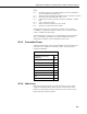
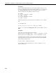
B.2.3 Transmitter Power
Transmitter output power is often expressed in dBm, which is a decibel power
rating relative to 1 milliWatt. The formula is: dBm = 10 log (Pt) with Pt
expressed in milliWatts.
TABLE B-2. Transmitter Power
Transmitter Power (Pt)
(milliWatts)
dBm
1 0
5 (RF401A series minimum) 7
10 10
50 17
100 20
250 (RF401A series maximum) 24
1000 30
5000 37
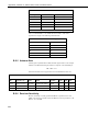
B.2.4 Cable Loss
Cable loss is a function of cable type, length, and frequency and is usually
specified as attenuation (dB) per 100 ft. of cable. Using a low loss cable
becomes very important as the cable run distances increase. Here are some
typical cable types and their properties:
B-3