
User Manual


Appendix B. Distance vs. Antenna Gain, Terrain, and Other Factors
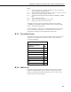
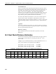
The following table helps select a Path Type in the above “Distance vs. Path
Loss” table to best fit your situation.
TABLE B-8. Path Type vs. Path
Characteristics Selector
Path Type Path Characteristics
2
nd
power Mountaintop to mountaintop
or Tall antenna towers
Line of sight
3
rd
power Dominantly line of sight
Low antenna heights
Some trees
4
th
power At water’s edge (very reflective)
Across field of grain (reflective)
Lots of Trees (absorptive)
B.4 Examples
Some examples will help illustrate the trade-offs in a link analysis. These
examples will all use the RF401A-series 900 MHz radio at maximum
transmitter power, and will use –106 dBm as the required power level at the
radio receiver. This is 3 dB higher than the quoted sensitivity of –109 dBm,
which will give us a 3 dB margin.
Here’s the equation we will use, from the first page:
Pt – Lt + Gt – Lp + Gr – Lr = Pr
Solved for Lp:
Lp = Pt – Lt + Gt + Gr – Lr – Pr
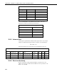
Example #1
Antenex FG9023 antennas on each end, 20 ft of LMR195 cable on one end,
10 ft of LMR195 on the other end, antennas at 10 ft height, fairly open terrain
with a few trees. How far can I go?
Pt = 24 dBm
Lt = 20 ft • (11.1 dB/100 ft) = 2.22 dB
Gt = Gr = 3 dBd = 5.15 dBi
Lr = 10 ft • (11.1 dB/100 ft) = 1.11 dB
Use –106 dBm for Pr
Lp = 24 – 2.22+ 5.15 + 5.15 – 1.11– (–106) = 137 dB
Use the 3
rd
to 4
th
power tables: Range from ~10 (4
th
power) to ~24 (3
rd
power)
miles
B-7