SDM-CD16S 16 Channel Solid State DC Control Module 1/08 C o p y r i g h t © 2 0 0 0 - 2 0 0 8 C a m p b e l l S c i e n t i f i c , I n c .
Warranty and Assistance The SDM-CD16S 16 CHANNEL SOLID STATE DC CONTROL MODULE is warranted by CAMPBELL SCIENTIFIC, INC. to be free from defects in materials and workmanship under normal use and service for twelve (12) months from date of shipment unless specified otherwise. Batteries have no warranty. CAMPBELL SCIENTIFIC, INC.'s obligation under this warranty is limited to repairing or replacing (at CAMPBELL SCIENTIFIC, INC.'s option) defective products.
SDM-CD16S Table of Contents PDF viewers note: These page numbers refer to the printed version of this document. Use the Adobe Acrobat® bookmarks tab for links to specific sections. 1. Function........................................................................1 2. Specifications ..............................................................2 3. Power Considerations.................................................3 4. Installation....................................................................4 4.
SDM-CD16S Table of Contents Tables 1. Datalogger to SDM-CD16S Connections .................................................. 6 2. Switch Position and Addresses ..................................................................
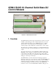
SDM-CD16S 16 Channel Solid State DC Control Module FIGURE 1. SDM-CD16S Face Panel 1. Function The SDM-CD16S has 16 DC voltage outputs that can be switched on and off manually or under datalogger control. Separate inputs for the power to the outputs (48 VDC max) and the power to SDM-CD16 logic (7 – 48 VDC) allow the option of powering the logic from the datalogger 12 V while switching a higher voltage. LEDs allow a visual indicator of active outputs.
SDM-CD16S 16 Channel Solid State DC Control Module Edlog dataloggers that support SDM-CD16 devices, I/O Instruction 104 is used (some old CR7s may use Instruction 29). In addition to SDM control, the SDM-CD16S has individual digital control inputs for each of the outputs. A logic high (5 V) on the control input will set the associated output high. The control input OR the SDM command can set the output high. Both the SDM command and the control input must be low for the port to be low.
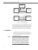
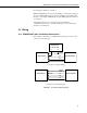
SDM-CD16S 16 Channel Solid State DC Control Module FIGURE 2. Equivalent Output Driver Circuit 3. Power Considerations The SDM-CD16S power requirements may be large compared to most CSI products. For most applications, an external power supply (see Figure 3) is recommended to power the SDM-CD16S. For some applications, it may be convenient to use the datalogger supply to power the SDM-CD16S (see Figure 3).
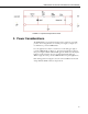
SDM-CD16S 16 Channel Solid State DC Control Module EXTERNAL 7 TO 48 VDC + — GND C1 SDM-CD16S DATALOGGER C2 C3 Connection with External Supply GND 12 V C1 C2 C3 SDM-CD16S DATALOGGER Connection with Datalogger Supply FIGURE 3. Connection Block Diagrams If the 21X power supply is used to power the SDM-CD16S Load Power, all low level analog measurements (thermocouples, pyranometers, thermopiles, etc.) must be made differentially.
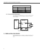
SDM-CD16S 16 Channel Solid State DC Control Module For datalogger connections, see Table 1. Multiple SDM-CD16Ss may be wired in parallel by connecting the datalogger side of one SDM-CD16S to the next. In most installations the total length of the cables connecting the SDM-CD16S and other SDM peripherals should not exceed 20 feet. Total cable lengths in excess of 20 feet may adversely influence communication performance. (For CR7 dataloggers, the total cable length should not exceed 600 feet.) 4.
SDM-CD16S 16 Channel Solid State DC Control Module TABLE 1. Datalogger to SDM-CD16S Connections SDM-CD16S Logic Power Logic Gnd C1 C2 C3 Datalogger 12 V on datalogger or 7 to 48 V external supply Gnd C1 (Control Port 1) C2 (Control Port 2) C3 (Control Port 3) Function Power Common ground Data Clock Enable 4.1.2 Controlled Device Connections In most applications, the SDM-CD16S acts as a switch (controllable break) in the positive supply of the circuit powering the controlled device.
SDM-CD16S 16 Channel Solid State DC Control Module TABLE 2. Switch Position and Addresses Switch Setting Base 10 Address CRBasic Dataloggers Base 4 Address Edlog Dataloggers 0 1 2 3 4 5 6 7 8 9 A B C D E F 0 1 2 3 4 5 6 7 8 9 10 11 12 13 14 15 00 01 02 03 10 11 12 13 20 21 22 23 30 31 32 33 6. Datalogger Instructions 6.1 CRBasic Dataloggers (CR800, CR850, CR1000, CR3000, CR5000, CR9000(X)) The SDMCD16AC instruction is used to control all versions of the SDMCD16.
SDM-CD16S 16 Channel Solid State DC Control Module CDCtrl(32) would be sent to port 16 on the second SDMCD16AC. If the Source parameter is defined as a Long variable, but it is dimensioned less than 16 * Reps, Source will act as a binary control for the instruction whose bits 0..15 will specify control ports 1..16, respectively. In this instance, Source(1) will be used for the first rep, Source(2) will be used for the second, and so on.
SDM-CD16S 16 Channel Solid State DC Control Module Instruction 29 – SDM-CD16S used with older CR7s Parameter 1 2 3 4 5 Type 2 2 2 2 4 Execution Time = Description Reps (No. of modules sequentially addressed) Device (2 = SDM-CD16S) Starting Address (base 4: 00..33) Card (Excitation card No.) Starting Input Location 150ms to 190ms per Rep The number of SDM-CD16Ss to be addressed is defined by the Reps (repetitions) parameter. Each Rep sequentially addresses (00, 01, 02,...
SDM-CD16S 16 Channel Solid State DC Control Module 8. Program Examples 8.1 Control Temperature and Fans – CR1000 In this example, the SDM-CD16S is used to control the temperature between 23° and 28°C in each of 5 greenhouses. In each greenhouse the SDM-CD16S controls a heating unit, a refrigerating unit, and an air-mixing fan according to the following conditions. Heating unit: Activate when temperature < 23.5°C. Deactivate when temperature > 25.5°C Cooling unit: Activate when temperature > 27.5°C.
SDM-CD16S 16 Channel Solid State DC Control Module The Example 1 program uses an array of values to set the SDM-CD16S control outputs: Program name: SDMCD16Example1.
SDM-CD16S 16 Channel Solid State DC Control Module The Example 2 program uses an integer instead of an array to set the SDMCD16S control outputs: 'Program name: SDMCD16Example2.CR1 'Date written: 6/25/2007 '\\\\\\\\\\\\\\\\\\\\\\\\\ DECLARATIONS ///////////////////////// Public Temp(5) Public TimedFanOn as Boolean Dim I as Long Dim CD16_Output as Long 'Note: CD16_Output bits set the SDM-CD16S ports.
SDM-CD16S 16 Channel Solid State DC Control Module Input Location assignments are as follows: Input Location Location Label Description 1..5 Temp #1..#5 Avg temp, greenhouse 1..5 10..14 Heat #1..#5 Heater control, greenhouse 1..5 SDM-CD16S Port 1..5 15..19 Cool #1..#5 Cooler control, greenhouse 1..5 SDM-CD16S Port 6..10 20..24 Fan #1..#5 Fan control, greenhouse 1..5 SDM-CD16S Port 11..
SDM-CD16S 16 Channel Solid State DC Control Module 9: Else (P94) 10: Z=F (P30) 1: 0 2: 0 3: 10-- Else, If the heater is off, F Exponent of 10 Z Loc : 11: End (P95) Enter a "0" into heater control location End Then Do/Else/End END HEATER CONTROL LOGIC START COOLER CONTROL LOGIC 12: If X<=>F (P89) 1: 1-X Loc 2: 3 >= 3: 27.
SDM-CD16S 16 Channel Solid State DC Control Module START FAN CONTROL LOGIC BASED ON HEATER/COOLER 22: If X<=>F (P89) 1: 10-X Loc 2: 2 <> 3: 0 F 4: 11 Set high Flag 1 If heater is on 23: If X<=>F (P89) 1: 15-X Loc 2: 2 <> 3: 0 F 4: 11 Set high Flag 1 If cooler is on 24: If Flag/Port (P91) 1: 11 Do if flag 1 is high 2: 30 Then Do If flag 1 is set 25: Z=F (P30) 1: 1 2: 0 3: 20-- Put a "1" into fan control location F Exponent of 10 Z Loc: 26: Else (P94) 27: Z=F (P30) 1: 0 2: 0 3: 20-- Set flag 1 The
SDM-CD16S 16 Channel Solid State DC Control Module 33: Beginning of Loop (P87) 1: 0 Delay 2: 5 Loop Count Start fan loop 34: Z=F (P30) 1: 1 2: 0 3: 20-- PUT A "1" INTO FAN CONTROL LOCATION F Exponent of 10 Z Loc : 35: End (P95) End fan loop 36: End (P95) End then do 37: If time is (P92) 1: 0 minutes into a 2: 15 minute interval 3: 22 Set low Flag 2 Reset flag 2 at the end of the 15 minute END FAN CONTROL LOGIC BASED ON TIME INPUT LOCATIONS 10 THROUGH 24 ARE NOW LOADED WITH "1" OR "0" TO SET PORT
SDM-CD16S 16 Channel Solid State DC Control Module The SiteSequence array also allows a site to be measured multiple times within the sequence. For some measurements it is necessary to measure calibration gases frequently (e.g., the concentration of various isotopes of CO2 with a trace gas analyzer.) The sequence in the example, with the six sample intakes and two calibration gases, is to measure 3 sample intakes, measure the zero and span, measure the other 3 intakes, and again measure the zero and span.
SDM-CD16S 16 Channel Solid State DC Control Module 'CR1000 Series Datalogger 'CR1000 Wiring: 'SDM Connections 'C1 'C2 'C3 'G ' '+12 SDM Data (green) SDM Clock (white) SDM Enable (brown) SDM reference (black) SDM shield (clear) Not Connected (Red) PipeLineMode Dim SiteSequence(10) As Long Dim SiteValve(8) As Long Dim SiteValveCD16 As Long 'The sequence consists of 10 valve settings 'There are 8 valve settings in the above sequence 'This is the variable that is used to set the SDM-CD16 Dim AvgDisable As
SDM-CD16S 16 Channel Solid State DC Control Module DataTable (SiteAvg,True,3000) DataInterval (0,30,Sec,10) CardOut(0,50000) Sample (1,SiteOutput,IEEE4) Average (2,GasConc(1),IEEE4,AvgDisable) Totalize (1,One,IEEE4,AvgDisable) EndTable BeginProg 'Load TGA Sample Selection Manifold SDM-CD16 Settings SiteValve(1) = &B00000001 'Site 1 Sample 1, SDM-CD16 out 1 SiteValve(2) = &B00000010 'Site 2 Sample 2, SDM-CD16 out 2 SiteValve(3) = &B00000100 'Site 3 = Sample 3, SDM-CD16 out 3 SiteValve(4) = &B00001000 'Site
SDM-CD16S 16 Channel Solid State DC Control Module EndIf Site = SiteSequence(SeqIndex) EndIf SiteValveCD16 = SiteValve(Site) EndOmit = Count > OmitCounts AvgDisable = NOT (EndOmit AND SeqActiveFlag) NextScan EndProg 8.4 Control Gas Sampling with Timing in Measurement Task – CR1000 8.4.1 The Purpose of this Example This example illustrates an instruction that can be used if: 1) There is a requirement for precisely timed switching in a known timing sequence.
SDM-CD16S 16 Channel Solid State DC Control Module In the example in Section 8.3, the logic that controls the SDM-CD16 is in the processing task. In the pipeline mode the measurements continue to occur at the proper time. If the processing falls behind the measurement the values used to set the SDM-CD16 will be updated only when the processing task gets to that point. This will be later than would be expected if the processing task were not falling behind.
SDM-CD16S 16 Channel Solid State DC Control Module 2. The sequence continues running as if nothing happened until the next occurrence of the sync interval (synced to the current clock) and then restarts. 3. Ignore the change in the clock, keep the current count and index proceeding as if nothing happened. When the TimedControl instruction is used within the program (i.
SDM-CD16S 16 Channel Solid State DC Control Module Public OmitCounts(8) As Long Dim I As Long Dim One DataTable (RawData,True,-1) DataInterval (0,0,Sec,10) CardOut (0 ,-1) Sample (1,Site,IEEE4) Sample (1,Count,IEEE4) Sample (1,SeqActiveFlag,IEEE4) Sample (2,GasConc(1),IEEE4) EndTable 'Site Table, output each time a site is completed.
SDM-CD16S 16 Channel Solid State DC Control Module 'Load Sequence Timing Array For I = 1 To 10 'Load the Valve and Timing Array with the valve Settings: ValveTime(I,1) = SiteValve(SiteSequence(I)) 'Load the Valve and Timing Array with the number of scans at each setting: ValveTime(I,2) = 30 Next I 'Initialize Variables One=1 SeqIndex=1 Count = 1 SeqActiveFlag = True Site = SiteSequence(SeqIndex) SiteOutput = Site Scan (1,Sec,10,0) 'Instructions to Measure Sensors Inserted Here.
This is a blank page.
Campbell Scientific Companies Campbell Scientific, Inc. (CSI) 815 West 1800 North Logan, Utah 84321 UNITED STATES www.campbellsci.com info@campbellsci.com Campbell Scientific Africa Pty. Ltd. (CSAf) PO Box 2450 Somerset West 7129 SOUTH AFRICA www.csafrica.co.za cleroux@csafrica.co.za Campbell Scientific Australia Pty. Ltd. (CSA) PO Box 444 Thuringowa Central QLD 4812 AUSTRALIA www.campbellsci.com.au info@campbellsci.com.au Campbell Scientific do Brazil Ltda.