SDM-CD8S 8 Channel Solid State DC Control Module Revision: 4/12 C o p y r i g h t © 2 0 0 9 - 2 0 1 2 C a m p b e l l S c i e n t i f i c , I n c .
Warranty “PRODUCTS MANUFACTURED BY CAMPBELL SCIENTIFIC, INC. are warranted by Campbell Scientific, Inc. (“Campbell”) to be free from defects in materials and workmanship under normal use and service for twelve (12) months from date of shipment unless otherwise specified in the corresponding Campbell pricelist or product manual. Products not manufactured, but that are re-sold by Campbell, are warranted only to the limits extended by the original manufacturer.
Assistance Products may not be returned without prior authorization. The following contact information is for US and international customers residing in countries served by Campbell Scientific, Inc. directly. Affiliate companies handle repairs for customers within their territories. Please visit www.campbellsci.com to determine which Campbell Scientific company serves your country. To obtain a Returned Materials Authorization (RMA), contact CAMPBELL SCIENTIFIC, INC., phone (435) 227-9000.
SDM-CD8S Table of Contents PDF viewers: These page numbers refer to the printed version of this document. Use the PDF reader bookmarks tab for links to specific sections. 1. Function........................................................................1 2. Specifications ..............................................................2 3. Power Considerations.................................................2 4. Installation....................................................................3 4.1 Wiring....
SDM-CD8S Table of Contents Tables 1. Datalogger to SDM-CD8S Connections .................................................... 4 2. Switch Position and Addresses ..................................................................
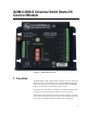
SDM-CD8S 8 Channel Solid State DC Control Module FIGURE 1. SDM-CD8S face panel 1. Function The SDM-CD8S has 8 DC voltage outputs and returns that can be switched on and off manually or under datalogger control. The “switch” is in the power return. The power Input (6-26 VDC) powers both the outputs and the SDMCD8 logic. LEDs allow a visual indicator of active outputs.
SDM-CD8S 8 Channel Solid State DC Control Module The SDM-CD8S is a synchronously addressed datalogger peripheral. Datalogger control ports 1, 2, and 3 are used to address the SDM-CD8S, then clock out the desired state of each of the 8 control ports. Up to 15 SDMCD8Ss may be addressed, making it possible to control a maximum of 120 ports from the datalogger’s first three control ports. The SDMCD16AC instruction is used to control the SDM-CD8S in CRBasic dataloggers.
SDM-CD8S 8 Channel Solid State DC Control Module If the datalogger lead acid supply is used, the current available from the wall charger limits the continuous output current. If the 21X power supply is used to power the SDM-CD8S Load Power, all low level analog measurements (thermocouples, pyranometers, thermopiles, etc.) must be made differentially. This is a result of slight ground potentials created along the 21X analog terminal strip when the 12 V supply is used to power peripherals.
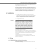
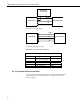
SDM-CD8S 8 Channel Solid State DC Control Module EXTERNAL 8 TO 26 VDC + — GND C1 SDM-CD8S DATALOGGER C2 C3 Connection to External Supply SDM-CD8S GND 12 V C1 C2 C3 DATALOGGER Connection to Datalogger Supply FIGURE 2. Connection block diagrams TABLE 1. Datalogger to SDM-CD8S Connections SDM-CD8S PWR Logic Gnd C1 C2 C3 Datalogger 12 V on datalogger or 8 to 26 V external supply Gnd C1 (Control Port 1) C2 (Control Port 2) C3 (Control Port 3) Function Power Common ground Data Clock Enable 4.1.
SDM-CD8S 8 Channel Solid State DC Control Module SDM_CD8S DC Power Supply PWR + + Out Load Power G GND Device - FIGURE 3. Typical wiring application 5. Address Selection Switch Each SDM-CD8S can have 1 of 16 addresses. Shipped from the factory, the address is set at 00. Table 2 shows switch position and the corresponding address. TABLE 2.
SDM-CD8S 8 Channel Solid State DC Control Module 6. Datalogger Instructions 6.1 CRBasic Dataloggers (CR800, CR850, CR1000, CR3000, CR5000, CR9000(X)) The SDMCD16AC instruction is used to control the SDM-CD8S and all versions of the SDM-CD16. SDMCD16AC (Source, Reps, SDMAddress) Remarks A port on an SDM-CD8S is enabled/disabled (turned on or off) by sending a value to it using the SDMCD16AC instruction. A non-zero value will enable the port; a zero value disables it.
SDM-CD8S 8 Channel Solid State DC Control Module NOTE CRBasic dataloggers use base 10 when addressing SDM devices. Edlog programmed dataloggers (e.g., CR10X, CR23X) used base 4 for addressing (Table 2). CRBasic dataloggers also have the TimedControl instruction which allows a timed sequence of settings to be managed by the measurement task avoiding possible processing delays to cause delayed switching (pipeline mode only). See an example in Section 8.4. 6.
SDM-CD8S 8 Channel Solid State DC Control Module For older CR7s with Instruction 29, the Device (parameter 2) specifies what type of synchronously addressed peripheral is to be addressed. The Device code for an SDM-CD8S is 2. For Instruction 29 only (older CR7s), the Card parameter (parameter 4) specifies which 725 Excitation Card is being used for the control port signals. The Reps parameter does not advance beyond the specified Card, requiring another Instruction 29 for each 725 Excitation Card used. 7.
SDM-CD8S 8 Channel Solid State DC Control Module Input Location assignments are as follows: Variable Array Description Temp(2) Avg temp, greenhouse 1 & 2 Heat(2) Heater control, greenhouse 1 & 2 SDM-CD8S Port 1 & 2 Cool(2) Cooler control, greenhouse 1 & 2 SDM-CD8S Port 3 & 4 Fan(2) Fan control, greenhouse 1 & 2 SDM-CD8S Port 5 & 6.
SDM-CD8S 8 Channel Solid State DC Control Module The Example 1 program uses an array of values to set the SDM-CD8S control outputs: 'Program name: SDMCD8Example.
SDM-CD8S 8 Channel Solid State DC Control Module The Example 2 program uses an integer instead of an array to set the SDMCD8S control outputs: 'Program name: SDMCD8Example2.CR1 'Date written: 6/25/2007 '\\\\\\\\\\\\\\\\\\\\\\\\\ DECLARATIONS ///////////////////////// Public Temp(2) Public TimedFanOn as Boolean Dim I as Long Dim CD16_Output as Long 'Note: CD16_Output bits set the SDM-CD8S ports.
SDM-CD8S 8 Channel Solid State DC Control Module Input Location assignments are as follows: Input Location Location Label Description 1, 2 Temp #1, 2 Avg temp, greenhouse 1, 2 11, 12 Heat #1, 2 Heater control, greenhouse 1, 2 SDM-CD8S Port 1, 2 13, 14 Cool #1, 2 Cooler control, greenhouse 1, 2 SDM-CD8S Port 3, 4 15, 16 Fan #1, 2 Fan control, greenhouse 1, 2 SDM-CD8S Port 5, 6 1: Beginning of Loop (P87) 1: 0 Delay 2: 2 Loop Count Master Loop, End Loop at Step 30 START HEATER CONTROL LOGIC 2
SDM-CD8S 8 Channel Solid State DC Control Module 10: Z=F (P30) 1: 0 2: 0 3: 11-- F Exponent of 10 Z Loc : 11: End (P95) Enter a "0" into heater control location End Then Do/Else/End END HEATER CONTROL LOGIC START COOLER CONTROL LOGIC 12: If X<=>F (P89) 1: 1-X Loc 2: 3 >= 3: 27.
SDM-CD8S 8 Channel Solid State DC Control Module START FAN CONTROL LOGIC BASED ON HEATER/COOLER 22: If X<=>F (P89) 1: 11-X Loc 2: 2 <> 3: 0 F 4: 11 Set high Flag 1 If heater is on 23: If X<=>F (P89) 1: 13-X Loc 2: 2 <> 3: 0 F 4: 11 Set high Flag 1 If cooler is on 24: If Flag/Port (P91) 1: 11 Do if flag 1 is high 2: 30 Then Do If flag 1 is set 25: Z=F (P30) 1: 1 2: 0 3: 15-- Put a "1" into fan control location F Exponent of 10 Z Loc: 26: Else (P94) 27: Z=F (P30) 1: 0 2: 0 3: 15-- Set flag 1 Then
SDM-CD8S 8 Channel Solid State DC Control Module 34: Z=F (P30) 1: 1 2: 0 3: 15-- F Exponent of 10 Z Loc : PUT A "1" INTO FAN CONTROL LOCATION 35: End (P95) End fan loop 36: End (P95) End then do 37: If time is (P92) 1: 0 minutes into a 2: 15 minute interval 3: 22 Set low Flag 2 Reset flag 2 at the end of the 15 minute END FAN CONTROL LOGIC BASED ON TIME INPUT LOCATIONS 10 THROUGH 24 ARE NOW LOADED WITH "1" OR "0" TO SET PORTS ON THE SDM-CD8S.
SDM-CD8S 8 Channel Solid State DC Control Module The sequence in the example, with the six sample intakes and two calibration gases, is to measure 3 sample intakes, measure the zero and span, measure the other 3 intakes, and again measure the zero and span. There are 10 sites in the sequence. (The SiteSequence array is dimensioned to 10 elements.) The sequence is 1, 2, 3, 7, 8, 4, 5, 6, 7, 8. Thirty seconds is spent on each site the sequence.
SDM-CD8S 8 Channel Solid State DC Control Module 'CR1000 Series Datalogger 'CR1000 Wiring: 'SDM Connections 'C1 'C2 'C3 'G ' '+12 SDM Data (green) SDM Clock (white) SDM Enable (brown) SDM reference (black) SDM shield (clear) Not Connected (Red) PipeLineMode Dim SiteSequence(10) As Long Dim SiteValve(8) As Long Dim SiteValveCD16 As Long 'The sequence consists of 10 valve settings 'There are 8 valve settings in the above sequence 'This is the variable that is used to set the SDM-CD16 Dim AvgDisable As Bo
SDM-CD8S 8 Channel Solid State DC Control Module DataTable (SiteAvg,True,3000) DataInterval (0,30,Sec,10) CardOut(0,50000) Sample (1,SiteOutput,IEEE4) Average (2,GasConc(1),IEEE4,AvgDisable) Totalize (1,One,IEEE4,AvgDisable) EndTable BeginProg 'Load TGA Sample Selection Manifold SDM-CD16 Settings SiteValve(1) = &B00000001 'Site 1 Sample 1, SDM-CD16 out 1 SiteValve(2) = &B00000010 'Site 2 Sample 2, SDM-CD16 out 2 SiteValve(3) = &B00000100 'Site 3 = Sample 3, SDM-CD16 out 3 SiteValve(4) = &B00001000 'Site 4
SDM-CD8S 8 Channel Solid State DC Control Module EndIf Site = SiteSequence(SeqIndex) EndIf SiteValveCD16 = SiteValve(Site) EndOmit = Count > OmitCounts AvgDisable = NOT (EndOmit AND SeqActiveFlag) NextScan EndProg 8.4 Control Gas Sampling with Timing in Measurement Task – CR1000 8.4.1 The Purpose of this Example This example illustrates an instruction that can be used if: 1) There is a requirement for precisely timed switching in a known timing sequence.
SDM-CD8S 8 Channel Solid State DC Control Module In the example in Section 8.3, the logic that controls the SDM-CD8S is in the processing task. In the pipeline mode the measurements continue to occur at the proper time. If the processing falls behind the measurement the values used to set the SDM-CD8S will be updated only when the processing task gets to that point. This will be later than would be expected if the processing task were not falling behind.
SDM-CD8S 8 Channel Solid State DC Control Module 2. The sequence continues running as if nothing happened until the next occurrence of the sync interval (synced to the current clock) and then restarts. 3. Ignore the change in the clock, keep the current count and index proceeding as if nothing happened. When the TimedControl instruction is used within the program (i.
SDM-CD8S 8 Channel Solid State DC Control Module Public OmitCounts(8) As Long Dim I As Long Dim One DataTable (RawData,True,-1) DataInterval (0,0,Sec,10) CardOut (0 ,-1) Sample (1,Site,IEEE4) Sample (1,Count,IEEE4) Sample (1,SeqActiveFlag,IEEE4) Sample (2,GasConc(1),IEEE4) EndTable 'Site Table, output each time a site is completed.
SDM-CD8S 8 Channel Solid State DC Control Module 'Load Sequence Timing Array For I = 1 To 10 'Load the Valve and Timing Array with the valve Settings: ValveTime(I,1) = SiteValve(SiteSequence(I)) 'Load the Valve and Timing Array with the number of scans at each setting: ValveTime(I,2) = 30 Next I 'Initialize Variables One=1 SeqIndex=1 Count = 1 SeqActiveFlag = True Site = SiteSequence(SeqIndex) SiteOutput = Site Scan (1,Sec,10,0) 'Instructions to Measure Sensors Inserted Here.
SDM-CD8S 8 Channel Solid State DC Control Module 24
Campbell Scientific Companies Campbell Scientific, Inc. (CSI) 815 West 1800 North Logan, Utah 84321 UNITED STATES www.campbellsci.com • info@campbellsci.com Campbell Scientific Africa Pty. Ltd. (CSAf) PO Box 2450 Somerset West 7129 SOUTH AFRICA www.csafrica.co.za • cleroux@csafrica.co.za Campbell Scientific Australia Pty. Ltd. (CSA) PO Box 8108 Garbutt Post Shop QLD 4814 AUSTRALIA www.campbellsci.com.au • info@campbellsci.com.au Campbell Scientific do Brazil Ltda.